
Negative voltage generator

a negative voltage and generator technology, applied in the field of negative voltage generators, can solve the problems of inferior sensibility of traditional negative voltage generators, problems such as the common problem of conventional negative voltage generators b>10/b>, and achieve the effect of stable output negative voltag

Inactive Publication Date: 2008-01-24
ETRON TECH INC
View PDF4 Cites 28 Cited by
  • Summary
  • Abstract
  • Description
  • Claims
  • Application Information

AI Technical Summary

Benefits of technology

[0022]Through the design of the invention, the control unit generates a control signal whose value depends on the negative voltage variation due to a ripple to track the negative voltage generated by charge pump, and thus the switching unit may keep the current passing through the switching unit constant according to the control signal and generate a stable output negative voltage as a result. Further, the negative voltage down converter is incorporated in the voltage mirror circuit to drive a high power device, and it is also able to avoid an unstable output negative voltage.

Problems solved by technology

However, during operation, the conventional negative voltage generator 10 often encounters problems as described below.
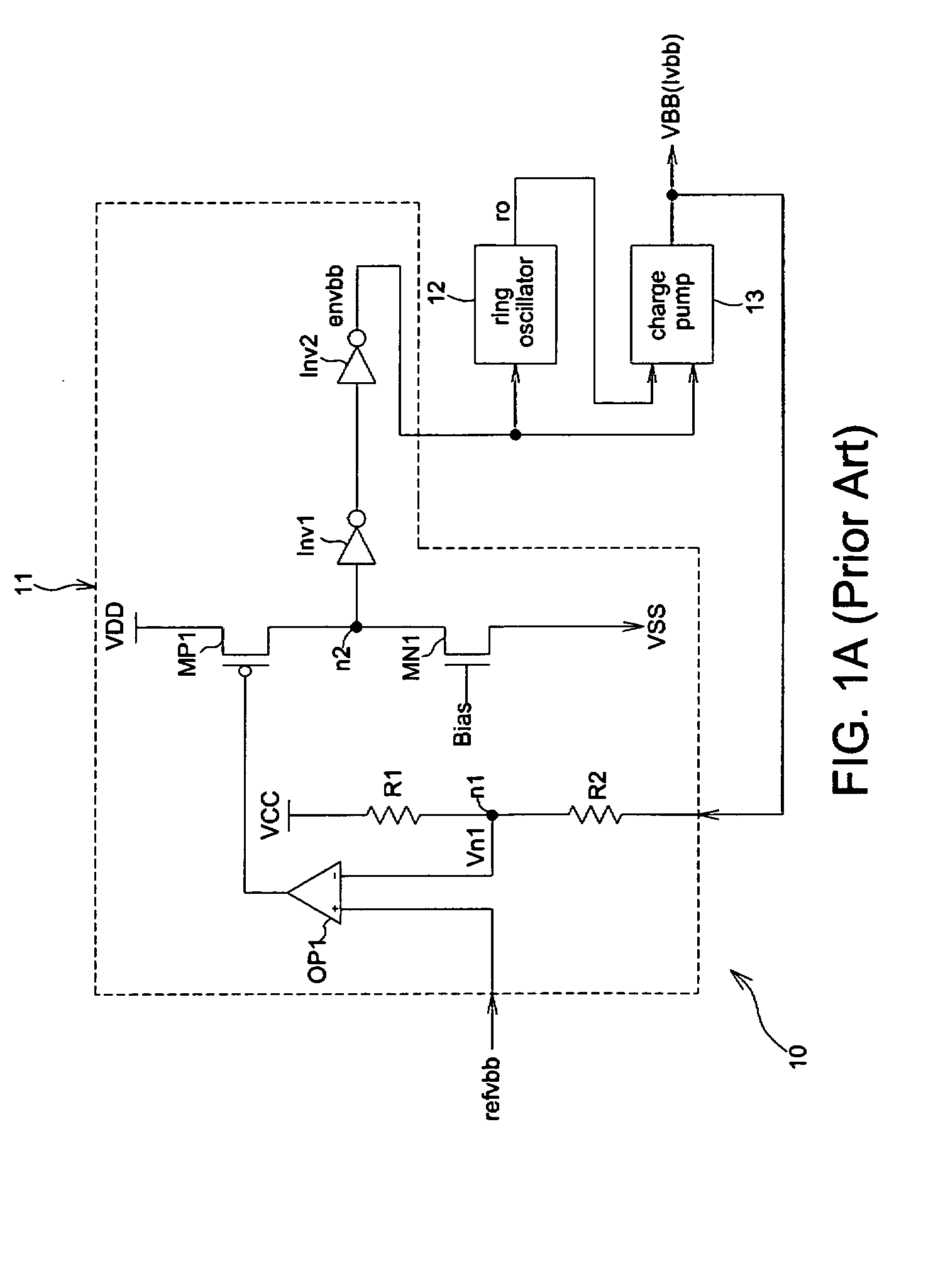
First, the sensibility of a typical level detector 11 is often unsatisfactory when it measures the output negative voltage VBB.
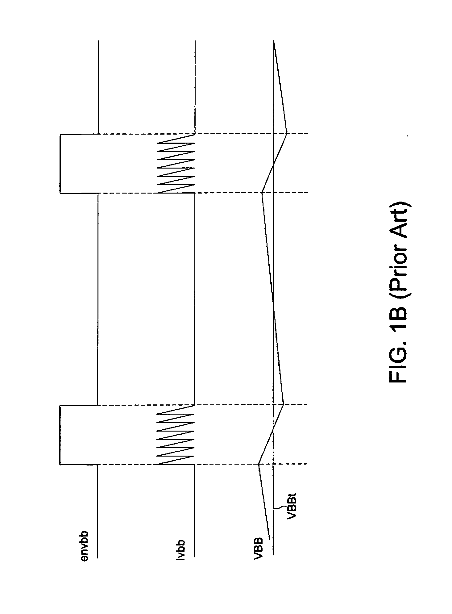
Hence, the measurement of a typical level detector 11 only reflects one-fourth of the negative voltage variation Δvbb, and this result causes an inferior sensibility in the traditional negative voltage generators.
Second, in the conventional negative voltage generator 10, the complex adjustment procedure for regulating the negative voltage VBB may cause a significant time delay.
Hence, the above complicated loop for signal transmission results in an obvious delay in signal response.
However, the voltage ripple really influences nowadays memory design that pursues high accuracy and requires only hundreds of millivolts of negatives voltage.
Hence, the layout areas and fabrication costs of the circuit are both considerable.

Method used


Image

  • Negative voltage generator
  • Negative voltage generator
  • Negative voltage generator

Examples


Embodiment Construction

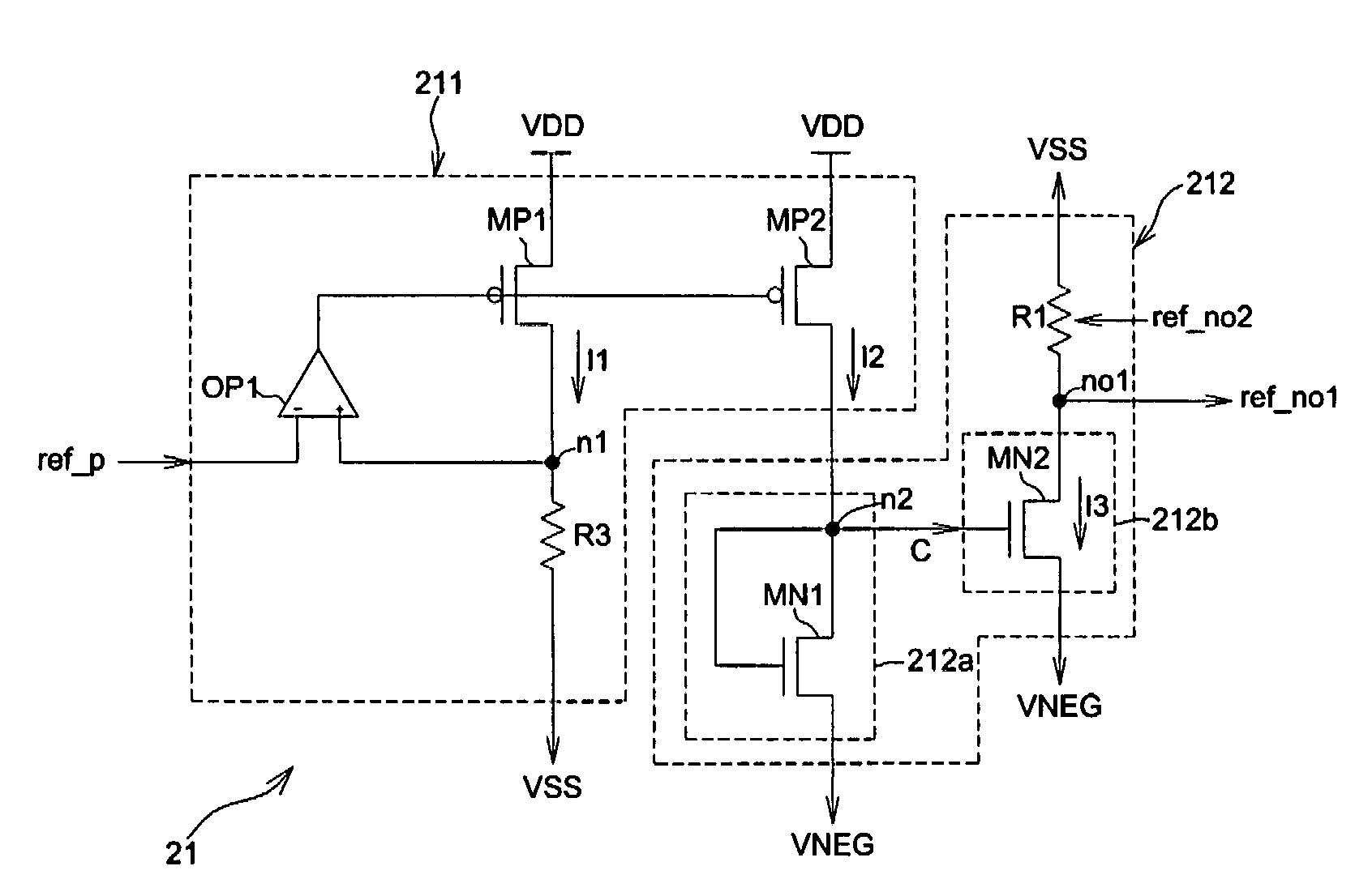
[0035]Referring to FIG. 2A, a negative voltage generator 20 of the invention includes a voltage mirror circuit 21, a negative voltage down converter 22, and a kick unit 23. The negative voltage generator 20 receives a source negative voltage VENG generated by a charge pump 13 and generates a stable output negative voltage VBB according to a positive reference voltage ref_p.

[0036]Referring to FIG. 2B, the voltage mirror circuit 21 receives the source negative voltage VENG generated by the charge pump 13 and generates a stable and fixed first output negative voltage ref_no1 according to the positive reference voltage ref_p. Alternatively, different levels of the negative voltage ref_no2 can be obtained by providing a tap on the resistor R1 shown in FIG. 2B.

[0037]The voltage mirror circuit 21 includes a first current mirror unit 211 and a second current mirror unit 212. The first current mirror unit 211 receives a fist positive voltage (high voltage level) from a first positive voltage...


PUM


Abstract

A negative voltage generator includes a current mirror unit, a control unit, a resistor, and a switching unit. The current mirror unit receives a first positive voltage from a first positive voltage source and a second positive voltage from a second positive voltage source and determines how to generate a first output current and a second output current according to the difference of a received positive reference voltage and the second positive voltage. The control unit generates a control signal whose value depends on the voltage variation of a negative voltage generated by a negative voltage source, and the on / off state of the switching unit is determined according to the control signal to keep the current passing through the switching unit constant and to generate a first output negative voltage having a constant level.

Description

BACKGROUND OF THE INVENTION[0001](a) Field of the Invention[0002]The invention relates to a negative voltage generator, particularly to a negative voltage generator capable of generating stable negative voltage.[0003](b) Description of the Related Art[0004]In typical memory architecture, different negative voltage levels generated by charge pump circuits of negative voltage generators are provided for specific components of a memory, such as word lines in a memory array.[0005]FIG. 1A shows a schematic diagram illustrating a conventional negative voltage generator 10. The negative voltage generator 10 includes a level detector 11, a ring oscillator 12, and a charge pump 13. The level detector 11 includes an operational amplifier OP1, two resistors R1 and R2, a PMOS transistor MP1, a NMOS transistor MN1, and two inverters Inv1 and Inv2. In the negative voltage generator 10, the charge pump 13 generates a negative voltage VBB, and the possible variation of the negative voltage VBB is d...

Claims


Application Information

Patent Timeline
IPC IPC(8): G05F3/16
CPCH02M3/073
Inventor HSU, JEN SHOU
Owner ETRON TECH INC
Learn More