
Claw Teeth Type Electric Rotary Machine and Manufacturing Method for Stators

a technology of electric rotary machines and manufacturing methods, which is applied in the direction of horology, instruments, and magnetic circuit shapes/forms/construction, etc., can solve the problems of large iron loss in the core of iron loss is produced, and the claw teeth type motor involves problems, so as to enhance the mechanical strength of the stator, avoid compressive deformation, and reduce the effect of core loss

Inactive Publication Date: 2008-01-24
JAPAN SERVO CO LTD +2
View PDF5 Cites 39 Cited by
  • Summary
  • Abstract
  • Description
  • Claims
  • Application Information

AI Technical Summary

Benefits of technology

[0009] To attain the above object, the invention is embodied as a claw teeth type electric rotary machine including a stator having an annular core with claws formed from a powder core and an annular coil installed inside the annular core, and a rotor rotatably positioned inside the stator. Therein, an inner edge of the annular core is provided with plural claw poles which are protruded at a predetermined interval in a circumferential direction and extended in an axial direction of the annular core so as to alternately meshes with each other; and the stator comprises the annular core with claws, the annular coil, and a molded nonmagnetic potting material filled between the annular core with claws and annular coil, so that the annular core with claws and annular coil are integrated with the molded potting material. Since the stator core and stator coil are integrated with molded material as the potting material, a gap between the annular coil and the annular core with claws is eliminated. This avoids compressive deformation and enhances the mechanical strength of the stator. Further, since the annular core with claws is formed of a powder core, a core loss can be reduced.
[0010] According to the invention, it is possible to provide a claw teeth type electric rotary machine and a manufacturing method for stators wherein the mechanical strength of a stator can be enhanced.

Problems solved by technology

However, this claw teeth type motor involves problems.
For this reason, a large iron loss is produced in the core of this motor.
Especially, since magnetic flux is concentrated on these bent portions, a large iron loss is produced there.
That is, the claw teeth type motor using SPCC, disclosed in JP-A-7-227075 (FIG. 2), is very inefficient.
However, stator cores using a powder core involve a problem of low mechanical strength.
For example, a powder core compact are 10 MPa in bending strength, which is lower than that of iron plates and the like, and are also susceptible to impact.

Method used


Image

  • Claw Teeth Type Electric Rotary Machine and Manufacturing Method for Stators
  • Claw Teeth Type Electric Rotary Machine and Manufacturing Method for Stators
  • Claw Teeth Type Electric Rotary Machine and Manufacturing Method for Stators

Examples


first embodiment

[0038] Description will be given to the structure of a claw teeth type motor (claw teeth type electric rotary machine) in an embodiment of the invention with reference to drawings.

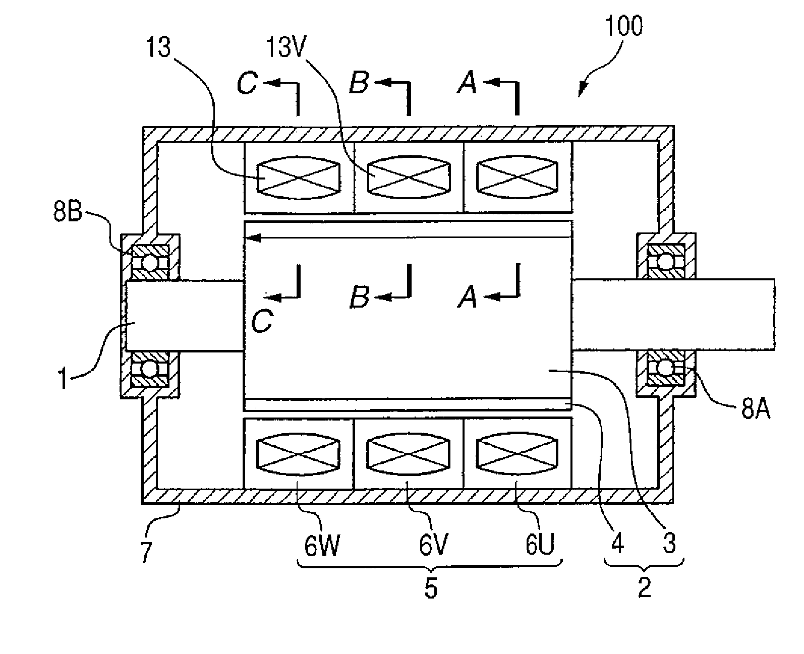
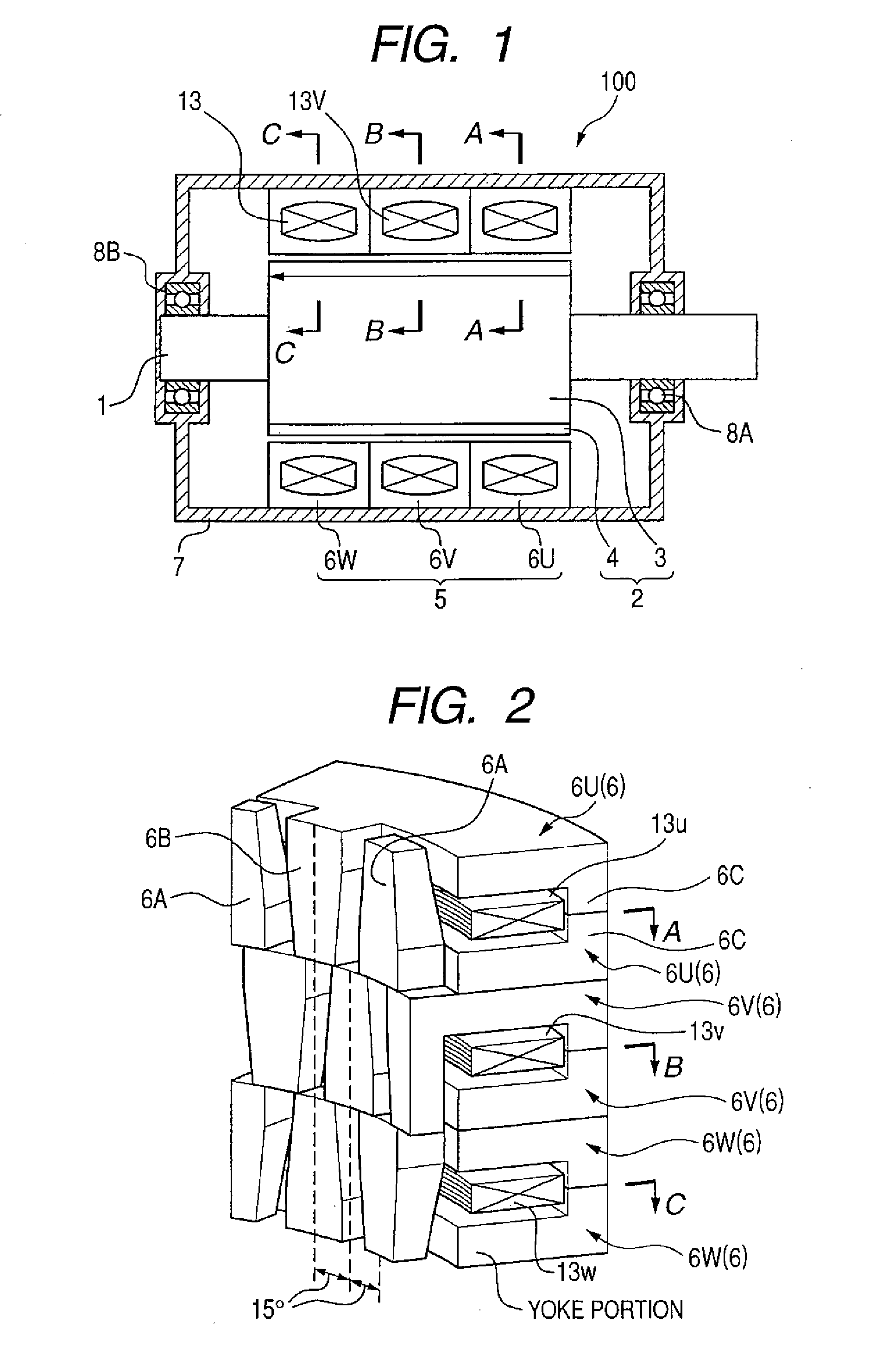
[0039] The claw teeth type motor 100 illustrated in the vertical sectional view in FIG. 1 is a polyphase motor of 16 poles and three phases. It includes: plural annular stators 5 provided in a housing (end bracket) 7; a rotor 2 with a shaft 1 positioned inside the annular stators wherein the shaft 1 is inserted into the rotor 2 in the annular stators; and bearings 8A, 8B which are fixed in the housing 7 and rotatably (revolvably) hold the shaft 1.

[0040] The rotor 2 has so-called ring magnet structure and is formed by magnetizing a ring-shaped ferromagnetic body in 16 poles to obtain a rotor core 3 and inserting (fixing) the shaft 1 into this rotor core by adhesive bonding or the like. The rotor 2 has its both axial ends rotatably supported by the bearings 8A, 8B in the housing 7. The stators 5 are fixed ...

second embodiment

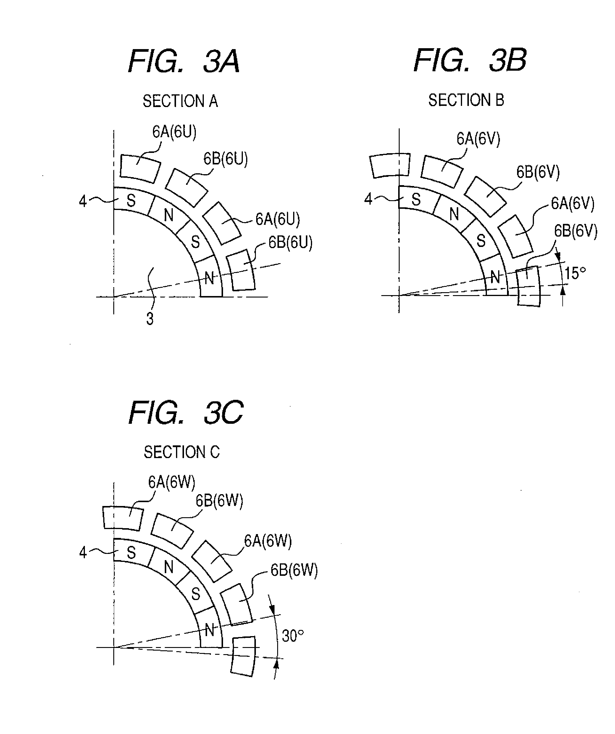
[0049] In the claw teeth type motor 100 in the first embodiment, the three independent stators 5 are disposed in alignment in the axial direction. (Refer to FIG. 1.) Therefore, an imbalance may occurs among phases. More specific description will be given as follows. The stators in two phases (u phase and w phase) positioned at both ends are so structured that one axial ends of their inner surfaces faced to the rotor magnet 4 are positioned close to the ends of the rotor magnet. On the other hand, the stator in the center phase (v phase) is so structured that neither of the axial ends of its inner surface faced to the rotor magnet is positioned close to the ends of the rotor magnet. This structure may break down the balance in terms of magnetic circuit. This imbalance causes unbalanced induced electromotive force to the coils 13. As a result, the efficiency of the motor may be reduced, and further cogging torque due to magnetic imbalance and torque pulsation during load operation may...

third embodiment

[0056] Description will be given to an embodiment in which cogging torque is reduced by providing stator cores 6 with a positioning mechanism to reduce a fabrication error. FIGS. 11B and 11C illustrate cogging torque produced when the position of a 24-pole motor is shifted with a positional error in the direction of rotation. In normal cases, one cycle of electrical angle corresponds to 30 degrees of mechanical angle. When the tolerance for fabrication is set to ±0.5 degrees or so, the amount of shift in electrical angle is ±6 degrees. FIGS. 11A to 11C illustrate an example where one phase is shifted by 0.5 degrees of mechanical angle due to a fabrication error. It will be assumed that the stators are assembled as illustrated in FIG. 11A. That is, the stator in phase A (u phase) is assembled as is shifted from the stator in phase B (v phase) by 10 degrees of mechanical angle. The stator in phase C (w phase), which should be shifted from the stator in phase B by 10 degrees, is assemb...


PUM

PropertyMeasurementUnit
electrical angleaaaaaaaaaa
bending strengthaaaaaaaaaa
mechanical angle=electrical angleaaaaaaaaaa

Abstract

A claw teeth type electric rotary machine comprises a stator including an annular core with claws formed from a powder core and an annular coil installed inside the annular core, and a rotor rotatably positioned inside the stator. An inner edge of the annular core is provided with plural claw poles which are protruded at a predetermined interval in a circumferential direction and extended in an axial direction of the annular core so as to alternately meshes with each other. The stator comprises the annular core with claws, the annular coil, and a molded nonmagnetic potting material filled between the annular core with claws and annular coil, so that the annular core with claws and annular coil are integrated with the molded potting non-magnetic material.

Description

CLAIM OF PRIORITY [0001] The present application claims priority from Japanese application serial no. 2006-200211 filed on Jul. 24, 2006, the contents of which are hereby incorporated by reference into this application. FIELD OF THE INVENTION [0002] The present invention relates to a claw teeth type electric rotary machine in which an annular coil is provided inside an annular core with claws and a manufacturing method for stators. BACKGROUND OF THE INVENTION [0003] Motors are used as equipment for driving that coverts electrical energy into mechanical energy for industrial use in the field of household appliances, the field of automobiles, and the like. In JP-A-2002-359938 (FIG. 9), for example, there is disclosed a slot type three-phase brushless motor because of its inexpensive structure, the simplicity of its drive circuit, and the like. There are various types of motors, single-phase, two-phase, and three-phase, and different types are used depending on applications. Especially...

Claims


Application Information

Patent Timeline
Patent Type & Authority Applications(United States)
IPC IPC(8): H02K1/04H02K37/14H02K1/12H02K15/00
CPCH02K1/04H02K1/145Y10T29/49009H02K15/022H02K15/12H02K3/325
Inventor ENOMOTO, YUJIITO, MOTOYAKITAMURA, MASASHIMASAKI, RYOSOYAMAZAKI, KATSUYUKIOHIWA, SHOJIMOTEGI, YASUAKIASAKA, KAZUOISHIHARA, CHIO
Owner JAPAN SERVO CO LTD
Learn More