
Apparatus and method for fire suppression

a technology of apparatus and fire suppression, applied in the field of fire suppression, can solve the problems of a large fire risk, a large amount of fuel lost through the penetration hole, and the passage of projectiles into the compartment, so as to prevent fire or extinguish fire

Inactive Publication Date: 2008-01-24
THE UNITED STATES OF AMERICA AS REPRESENTED BY THE SECRETARY OF THE NAVY
View PDF9 Cites 7 Cited by
  • Summary
  • Abstract
  • Description
  • Claims
  • Application Information

AI Technical Summary

Benefits of technology

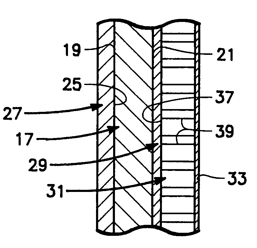
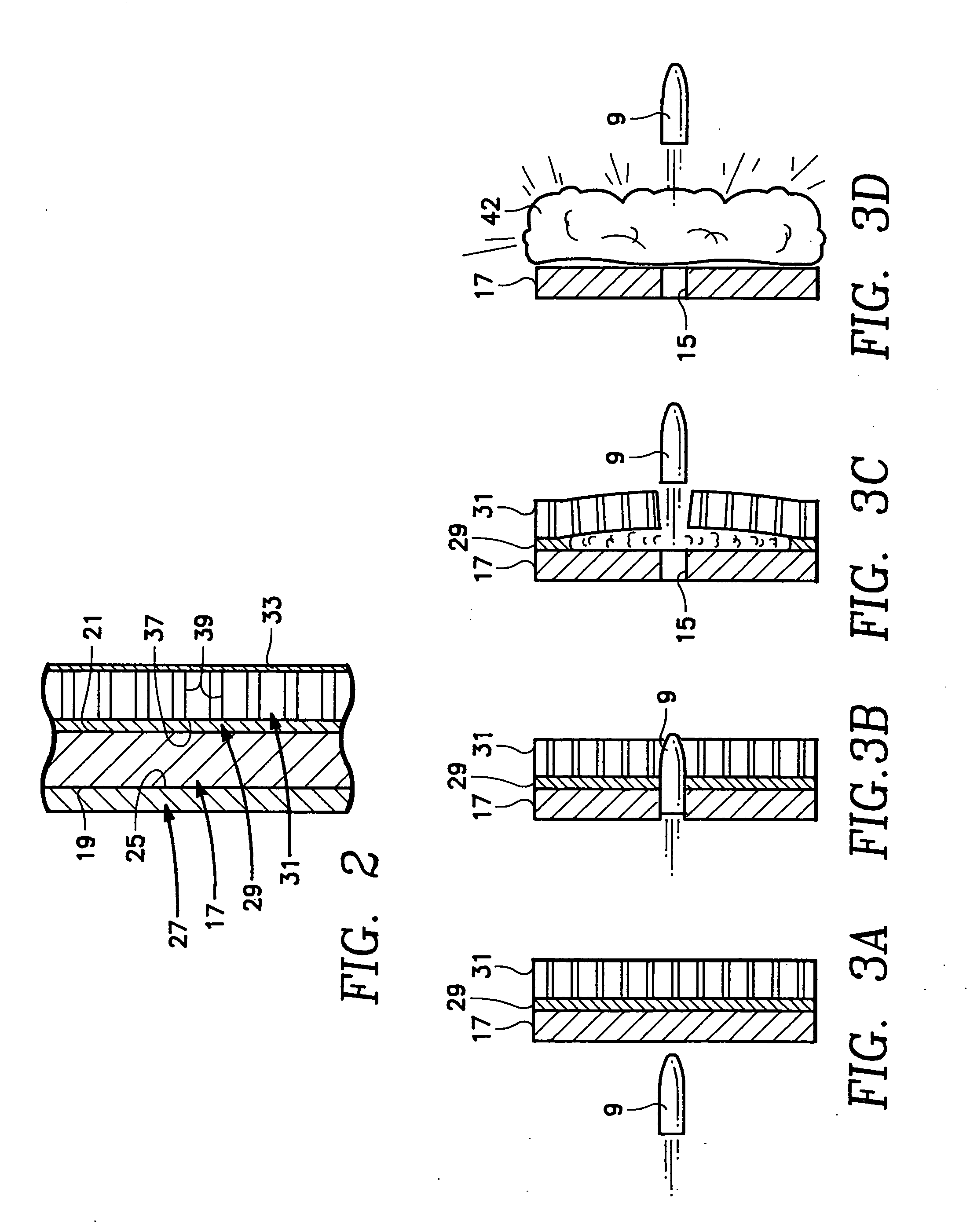
[0016] An embodiment of the invention includes an apparatus and a method for fire suppression including the utilization of a very powerful explosive composition, such as CL20, layered between a fire suppressant panel such as a powder panel and another fixed structure such as a fuel tank dry bay wall. Upon impact or other means of detonation the explosive composition shatters a large number of cells in the panel, very quickly dispersing the fire suppressant substance, thereby extinguishing or preventing a fire from occurring.

Problems solved by technology

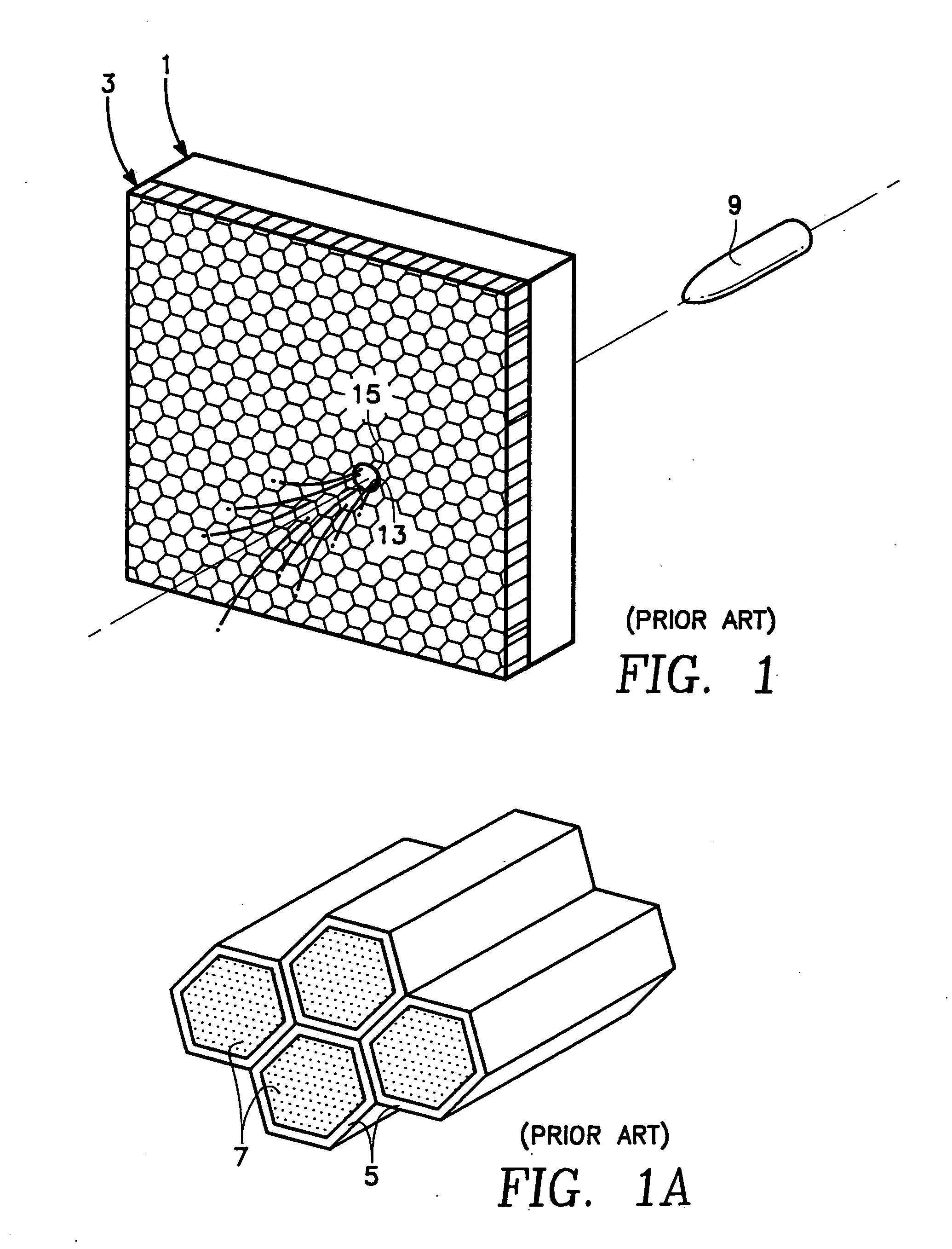
When this occurs, such as in the case of a self-sealing fuel tank, some amount of fuel is lost through the penetration hole before the sealing material can seal the hole against further leakage.
In other situations, the projectile can strike a surface in the penetrated compartment and the friction or flash of the strike can start a fire in the compartment.
Passage of the projectile into the compartment therefore poses a significant fire risk.
In many vessels, such as in aircraft, compartments adjacent to fuel tanks may carry important steering, navigational, and control components that could be greatly damaged by a fire started when a bullet crashes through the walls of the fuel tank and into the adjacent compartment.
In other situations, the mere entry of the projectile and striking of one of the components can cause a fire that can possibly do more damage than the initial penetration and collision with the equipment.
This allows very little fire suppressant to be available to follow the leaked fuel or reach the flammable substances in the compartment.
Subsequently it has been demonstrated that BTATz was unsuitable for exploding and dispersing the fire suppressant powder.
However, the reaction rate of BTATz is not fast enough to pressurize a panel and shatter a large area of the panel.
When gases are not generated quickly enough they dissipate along the same non-obstructed path resulting in a less effective disruption of the panel.
Therefore the process discussed by Bennett using BTATz would not result in more effective fire suppression.

Method used


Image

  • Apparatus and method for fire suppression
  • Apparatus and method for fire suppression
  • Apparatus and method for fire suppression

Examples


Embodiment Construction

[0024] An embodiment of the invention relates to an apparatus and a method for fire suppression including the utilization of a powerful explosive composition, such as CL20, layered between a fire suppressant panel such as, for example, a powder panel and another fixed structure such as a fuel tank dry bay wall. Upon impact or other means of detonation the explosive composition causes the rupture of a large number of cells in the panel, dispersing the fire suppressant substance, thereby extinguishing or preventing fire.

[0025] Before explaining the disclosed embodiments of the invention in detail it is to be understood that the invention is not limited in its application to the details of the particular arrangement shown since the invention is capable of other embodiments. Also, the terminology used herein is for the purpose of description and not of limitation.

[0026] Referring to the drawings, wherein elements are identified by numbers and like elements are identified by like numbe...


PUM


Abstract

An embodiment of the invention includes an apparatus and a method for fire suppression including the utilization of an explosive composition layered between a fire suppressant panel such as, for example, a powder panel and another fixed structure such as, for example, a fuel tank dry bay wall. Upon impact or other means of detonation the explosive composition effects the rupture of a large number of frangible cells in the panel, dispersing the fire suppressant substance, thereby extinguishing or preventing fire.

Description

[0001] This application is a continuation-in-part of U.S. patent application Ser. No. 10 / 774,660, filed Feb. 3, 2004.STATEMENT REGARDING FEDERALLY SPONSORED RESEARCH OR DEVELOPMENT [0002] The invention described herein may be manufactured and used by or for the government of the United States of America for governmental purposes without the payment of any royalties thereon or therefor.FIELD OF THE INVENTION [0003] This invention pertains to the field of fire suppression. More particularly, it pertains to the field of fire suppression panels. BACKGROUND OF THE INVENTION [0004] In any compartment, there is always the possibility of penetration from a projectile. When this occurs, such as in the case of a self-sealing fuel tank, some amount of fuel is lost through the penetration hole before the sealing material can seal the hole against further leakage. In other situations, the projectile can strike a surface in the penetrated compartment and the friction or flash of the strike can st...

Claims


Application Information

Patent Timeline
IPC IPC(8): A62C2/00
CPCA62C3/065A62C3/08A62C35/08Y10T428/24157B64D2037/325Y10S428/92B64D37/32
Inventor FALLIS, STEPHENMANCHOR, JOSEPH A.MEYERS, GARY W.
Owner THE UNITED STATES OF AMERICA AS REPRESENTED BY THE SECRETARY OF THE NAVY
Learn More