
Secret communications system and channel control method

a communication system and channel control technology, applied in the field of secret communication systems, can solve the problems of cryptanalysis requiring a large amount of calculation, quantum channel portion point-to-multipoint connection, and secret degradation, and achieve the effect of efficient photon transmission, quantum key generation and sharing, and ensuring the amount of encryption key and the stability of encrypted communication

Active Publication Date: 2008-01-17
NEC CORP
View PDF3 Cites 70 Cited by
  • Summary
  • Abstract
  • Description
  • Claims
  • Application Information

AI Technical Summary

Benefits of technology

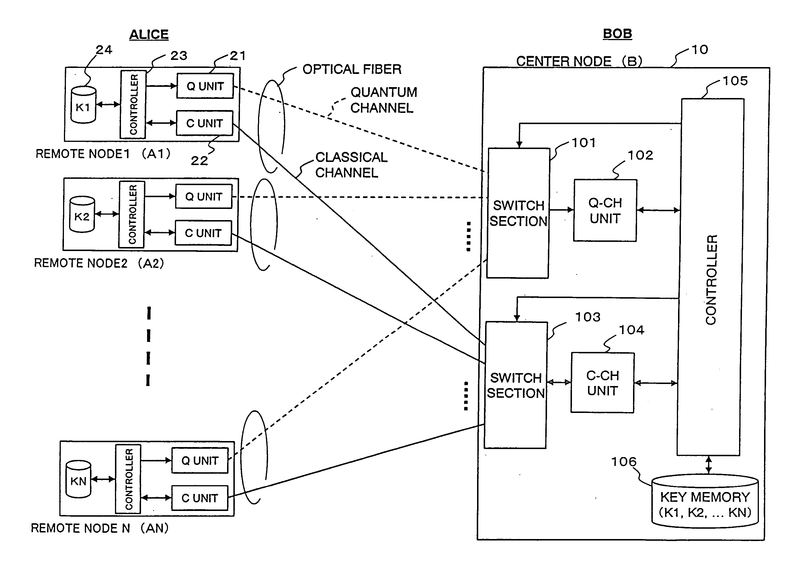
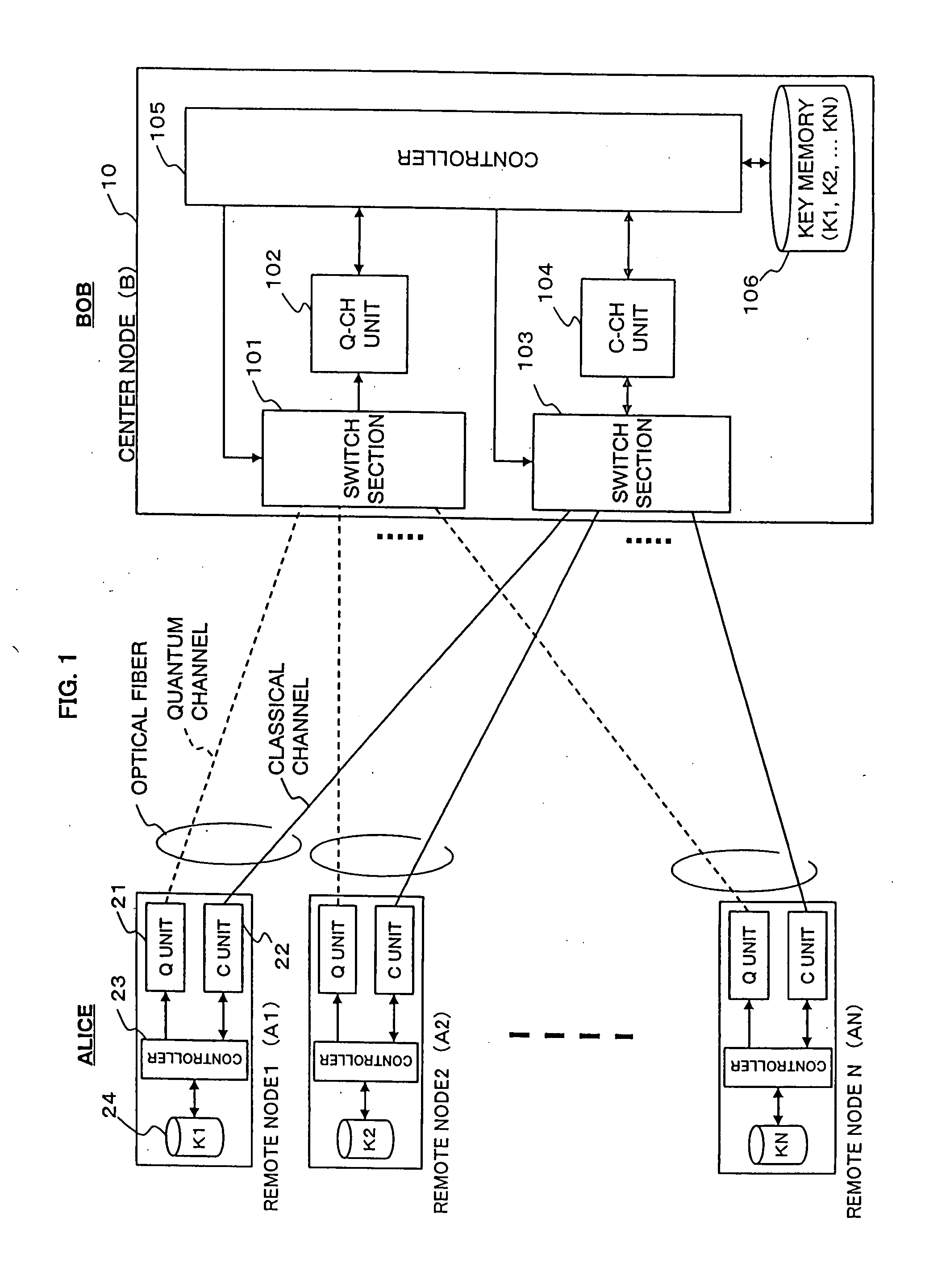
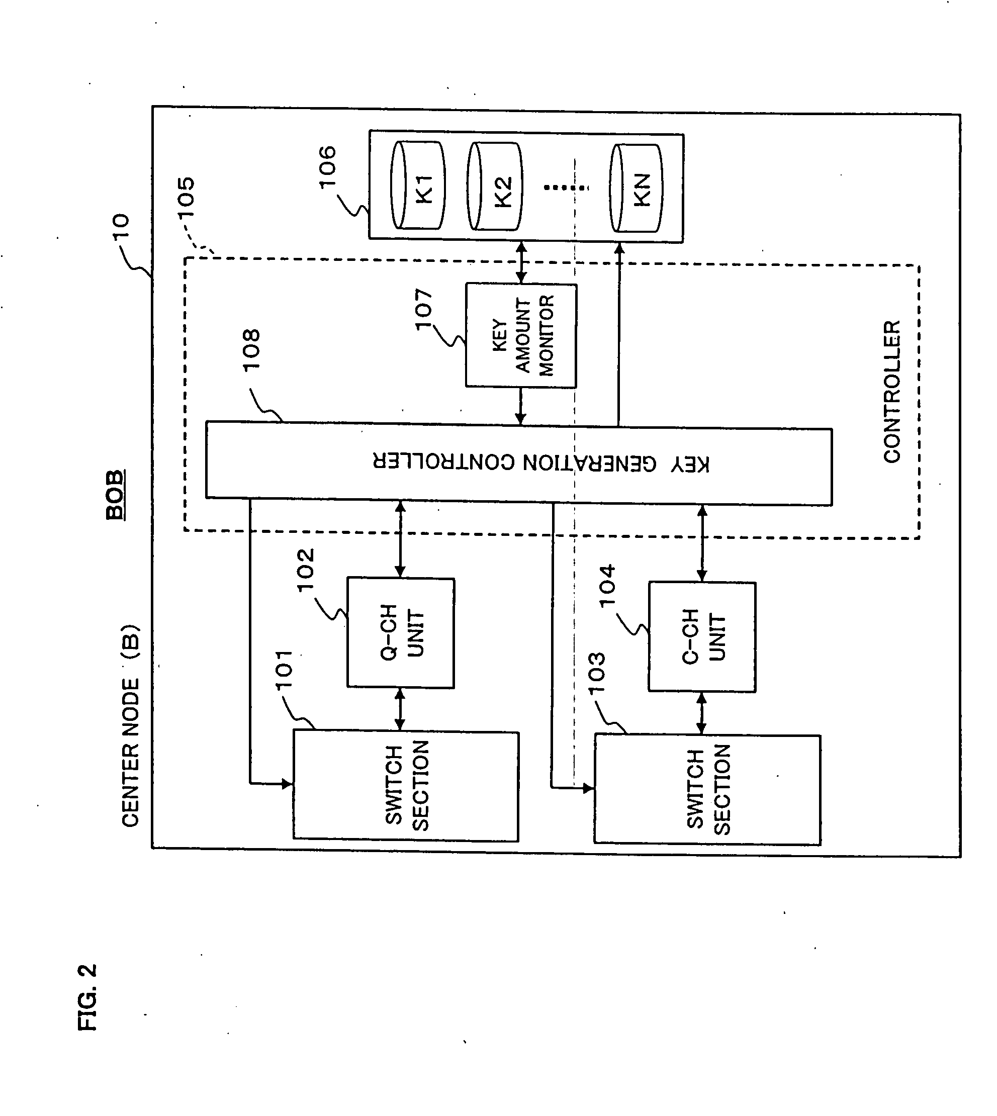
The present invention is a secret communications system that uses random numbers as a cryptographic key for encryption communication. The system includes a center node and multiple remote nodes connected through optical transmission lines. The center node generates and shares the random numbers with each remote node, and the remote nodes use these shared random numbers for cryptographic communication. The system includes switches that independently switch between the remote nodes for generating the shared random numbers and the cryptographic communication. The switches are controlled based on the amount of shared random numbers for each remote node or the consumption rate of the shared random numbers. The system can be used in a quantum key distribution system, where the quantum and classical channels are separately handled by the switches, allowing for efficient photon transmission, quantum key generation, and sharing, as well as encrypted communication in point-to-multipoint or multipoint-to-multipoint connections. The system is cost-effective for fiber laying and can be used in a variety of network configurations.

Problems solved by technology

Therefore, it is an important issue to devise preventive measures to protect the data flowing over networks from risks of eavesdropping.
Since this scheme is not suitable for high-speed processing, it is used to distribute a cryptographic key for the private key scheme.
The security according to any of these methods depends on the fact that an enormous amount of calculation is required for cryptanalysis.
Therefore, there has been a problem that the secrecy is degraded with improvements in cryptanalysis technology, such as an improvement in computer performance and the advent of an evolved cryptanalysis algorithm.
However, according to the technologies to date, only point-to-multipoint connections of the quantum-channel portion has been realized.
The hitherto technologies could not satisfy such a condition.
In addition, if a network is built by using different fibers for quantum channels and classical channels respectively, the problems arise not only that the cost of fiber laying increases but also that an action of eavesdropping on the classical channel fiber cannot be detected.

Method used


Image

  • Secret communications system and channel control method
  • Secret communications system and channel control method
  • Secret communications system and channel control method

Examples


first embodiment

1.4) First Embodiment

[0061]FIG. 4 is a block diagram showing a schematic configuration of a secret communications system according to a first embodiment of the present invention. Here, remote nodes 100-1 to 100-N are individually connected to a center node 200 through optical fiber transmission lines 300-1 to 300-N, respectively.

[0062] Each remote node 100-i (i=1, 2, . . . , N) includes a key generator (Key Gen.) 110-i, a quantum transmitter (QTx) 120-i, an optical multiplexer / demultiplexer 130-i, a classical transceiver (CTRx) 140-i, an encoder / decoder (Encode / Decode) 150-i, and a key memory 160-i. The key memory 160-i stores a shared random-number string Ki generated between its own remote node 100-i and the center node 200.

[0063] The center node 200 includes a key generator (Key Gen.) 210, a quantum receiver (Q_Rx) 220, optical multiplexers / demultiplexers 230-1 to 230-N, a classical transceiver (CTRx) 240, an encoder / decoder (Encode / Decode) 250, a key memory 260, optical switch...

example i

[0070] Next, a specific example will be described in which the above-described first embodiment is applied to a plug and play quantum key distribution (QKD) system.

[0071]FIG. 5A is a block diagram showing an example of a quantum transmitter on Alice's side (remote-node side) in a plug and play QKD system. FIG. 5B is a block diagram showing an example of a quantum receiver on Bob's side (center-node side) in the plug and play QKD system. The quantum transmitter 30 and the quantum receiver 40 shown in FIGS. 5A and 5B respectively are of the alternative-shifted phase modulation, plug and play type (see Ribordy et al., as well as Tanaka, A., Tomita, A., Tajima, A., Takeuchi, T., Takahashi, S., and Nambu, Y., “Temperature independent QKD system using alternative-shifted phase modulation method” in Proceedings of European Conference on Optical Communication (2004), Tu4.5.3).

[0072] In this example, the quantum transmitter 30 includes a polarization beam splitter (PBS) 31, a phase modulat...

second embodiment

1.5) Second Embodiment

[0083]FIG. 7 is a block diagram showing a schematic configuration of a secret communications system according to a second embodiment of the present invention. Here, remote nodes 100-1 to 100-N are individually connected to a center node 201 through optical fiber transmission lines 300-1 to 300-N, respectively. The configuration of each remote node 100-i is substantially the same as that in the first embodiment shown in FIG. 4, and therefore description thereof will be omitted.

[0084] The center node 201 includes a key generator (Key Gen.) 210, a quantum receiver (Q_Rx) 220, optical multiplexers / demultiplexers 230-1 to 230-N, classical transceivers (CTRx) 241-1 to 241-N, an encoder / decoder (Encode / Decode) 250, a key memory 260, an optical switch 271, an electrical switch 273, and switch controllers 280 and 291. As in the first embodiment, a quantum channel and a classical channel use mutually different wavelengths. Wavelength multiplexing and demultiplexing are ...


PUM


Abstract

A secret communications system realizes point-to-multipoint or multipoint-to-multipoint connections of both quantum channels and classical channels. Multiple remote nodes are individually connected to a center node through optical fiber, and random-number strings K1 to KN are individually generated and shared between the respective remote nodes and the center node. Encrypted communication is performed between each remote node and the center node by using the corresponding one of the shared random-number strings K1 to KN as a cryptographic key. The center node is provided with a switch section for quantum channels and a switch section for classical channels. Switching control on each of these switch sections is performed independently of the other by a controller.

Description

BACKGROUND OF THE INVENTION [0001] 1. Field of the Invention [0002] The present invention relates to a secret communications system and, more particularly, to a secret communications system, secret communication apparatus, and channel control method, enabling point-to-multipoint and / or multipoint-to-multipoint cryptographic key sharing and encrypted communication. [0003] 2. Description of the Related Art [0004] In recent years, the internet has been economic and social infrastructure over which various data are exchanged. Therefore, it is an important issue to devise preventive measures to protect the data flowing over networks from risks of eavesdropping. One of the preventive measures is a secret communications system by which data for communication is encrypted. For the encryption method, there are two kinds of schemes: private key cryptography and public key cryptography. [0005] The private key cryptography, as is typified by AES (Advanced Encryption Standard), is a scheme using...

Claims


Application Information

Patent Timeline
Patent Type & Authority Applications(United States)
IPC IPC(8): H04L9/08H04L9/28
CPCH04L9/0855H04L9/0852Y04S40/20
Inventor TAJIMA, AKIOTANAKA, AKIHIROMAEDA, WAKAKOTAKAHASHI, SEIGO
Owner NEC CORP
Learn More