
Magnetic resonance system and method for cardiac imaging

a magnetic resonance system and cardiac imaging technology, applied in the field of cardiac imaging methods, can solve the problems of difficult cardiac imaging, time-consuming and laborious, and the threshold for operating personnel who are not health professionals to conduct heart examinations is therefore very large, and achieves the effect of less time-consuming and more cost-efficien

Active Publication Date: 2008-01-10
SIEMENS HEALTHCARE GMBH
View PDF3 Cites 17 Cited by
  • Summary
  • Abstract
  • Description
  • Claims
  • Application Information

AI Technical Summary

Benefits of technology

[0008] An object of the present invention is to provide a method for representation of the heart by means of magnetic resonance tomography, which can be implemented by less-trained personnel and that is less time-consuming (and therefore more cost-efficient).
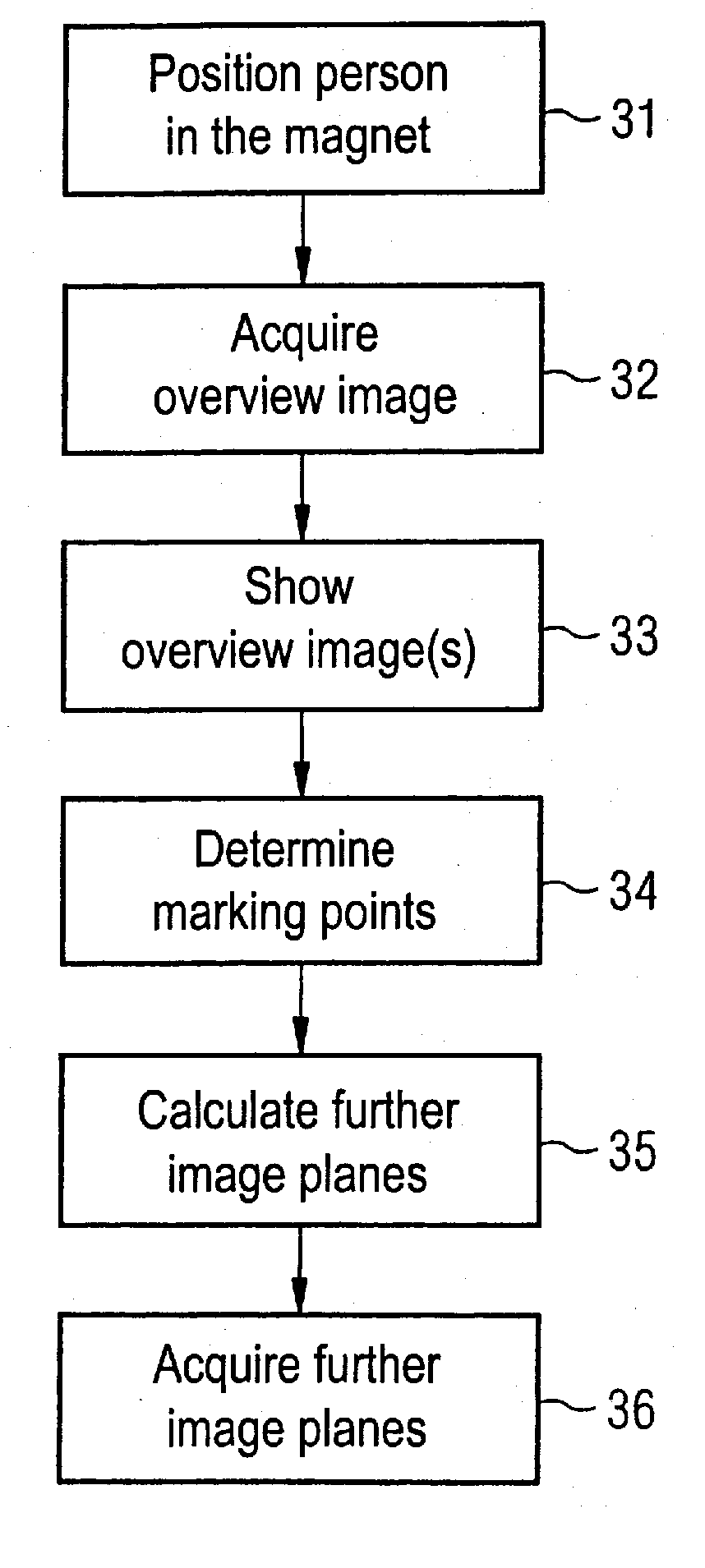
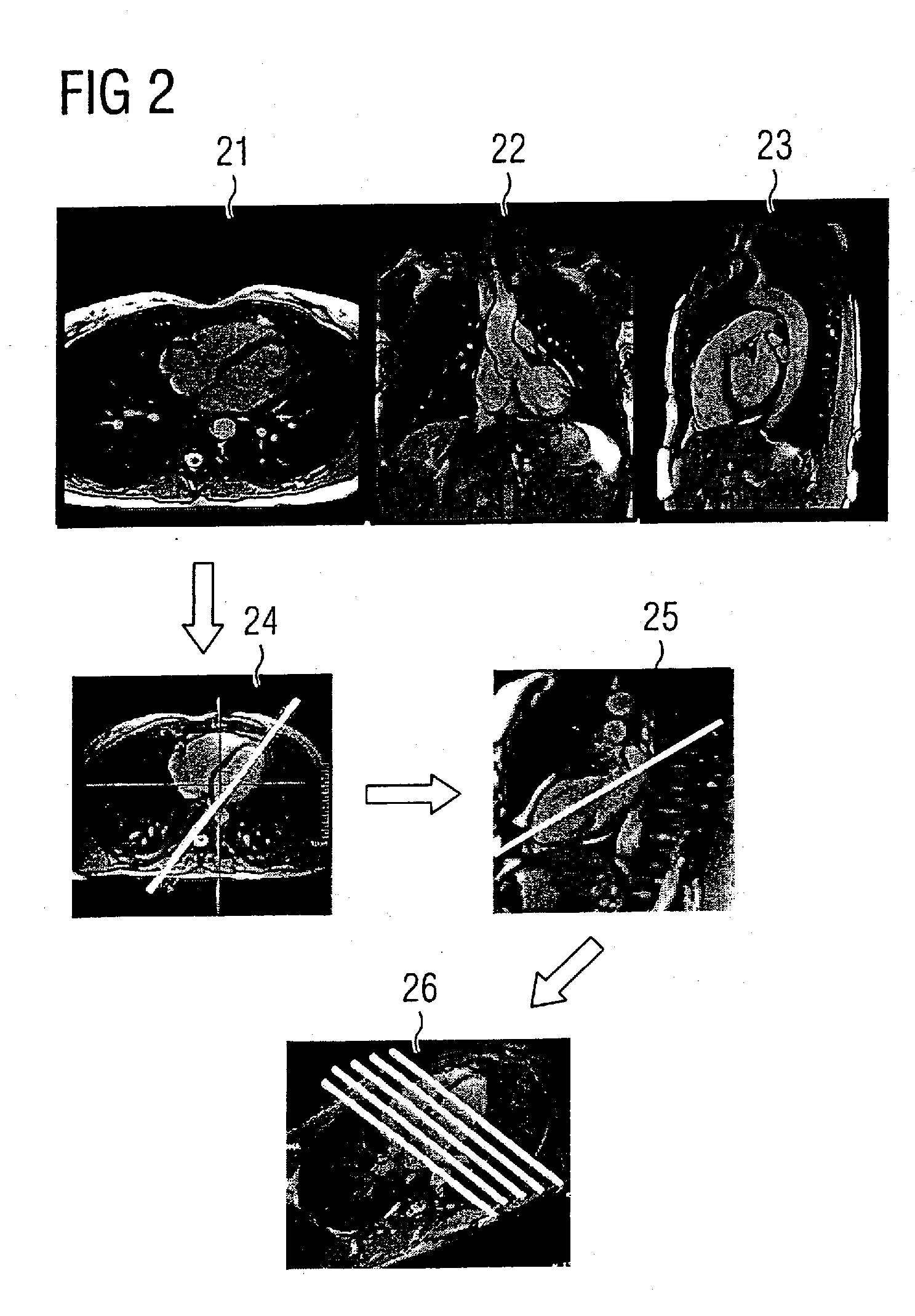
[0009] This object is achieved in accordance with the invention by a method for representation of the heart in a magnetic resonance system, wherein at least one MR overview image of the heart is acquired in a first step, whereby an image plane with a predetermined position relative to the magnetic resonance system being selected for this overview image. An MR overview image is subsequently acquired in this one predetermined image plane, this MR overview image being subsequently shown on the MR system display for the operating personnel. A number of marking points then can be established on the displayed overview image that was acquired in a predetermined position. After the marking points have been established, further image planes for representation of the heart are automatically calculated using some of the established marking points. Further MR images of the heart are subsequently acquired in the calculated image planes. The method according to the present invention has the advantage that further overview images in various positions no longer have to be acquired, as described in connection with FIG. 2. It is only still necessary to acquire a first overview exposure in a specific, established position. Studies have shown that there is a specific orientation of the image plane relative to the patient in which MR images of the heart can be generated that can then subsequently be used (by establishment of a few marking points) in order to automatically determine the other image planes. The heart orientation and position do in fact vary from patient to patient, but so little that this same slice orientation can be selected independently of the patient.
[0016] The marking points advantageously can also be used to improve automatic segmentation algorithms. For example, the myocardium is segmented in many applications. If the position of some of these marking points is now known, a segmentation algorithm can be improved when some of these marked anatomical points are established. It is also possible to automatically implement segmentation algorithms on the images of the pseudo-short axis slice and then to calculate and to display markings as start values for the individual marking points, based on the results of the automatic segmentation. The final determination of the marking points thus is made simpler for operating personnel.

Problems solved by technology

The inhibition (reluctance) threshold (in particular for operating personnel who are not health professionals) to conduct heart examinations is therefore very large.
Furthermore, even for trained personnel heart examinations are very complicated since various steps are necessary in order to find the ideal image planes.
As is apparent from the above description, the localization of the heart is time-consuming and requires medically-trained operating personnel.

Method used


Image

  • Magnetic resonance system and method for cardiac imaging
  • Magnetic resonance system and method for cardiac imaging
  • Magnetic resonance system and method for cardiac imaging

Examples


Embodiment Construction

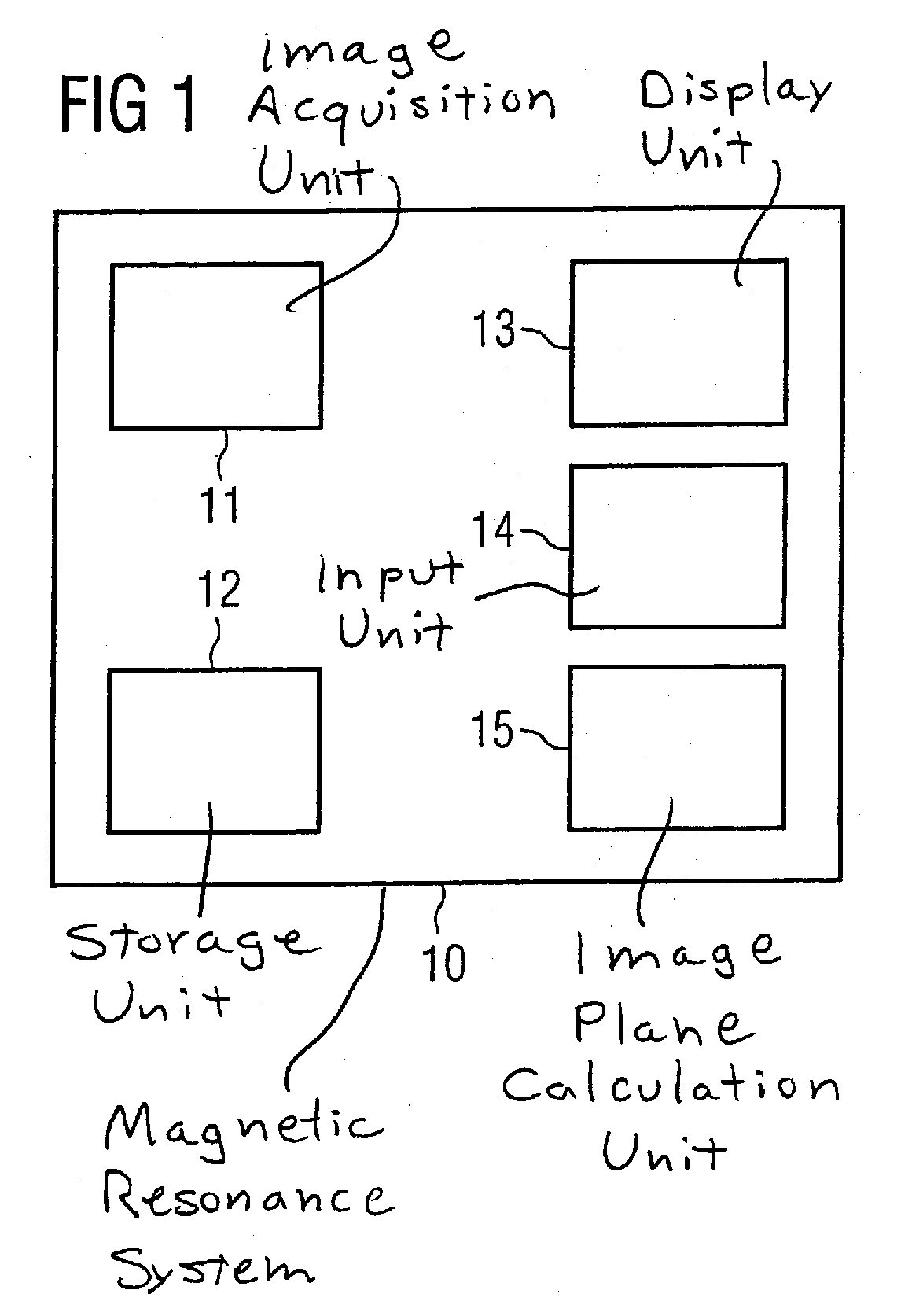
[0023]FIG. 1 schematically shows a magnetic resonance (MR) system 10. The basic design and the interaction of the various components of a magnetic resonance system (such as, for example, basic field magnet, gradient coils, RF irradiation with radio-frequency antenna, reception antenna etc.) are known to those skilled in the art and need not be described further herein since they are not of importance for the understanding of the invention. Only the components that are necessary for the understanding of the invention are described here. The schematic magnetic resonance system 10 shown in FIG. 1 includes an image acquisition unit 11 for acquisition of the MR images, in particular here the overview image. Naturally the other MR images are also acquired with the image acquisition unit 11. Furthermore, a storage unit 12 is provided in which at least the predetermined orientation and position of the image plane relative to the middle of the magnet of the resonance system is stored. The MR...


PUM


Abstract

In a method for representation of the heart in a magnetic resonance system at least one MR overview image of the heart is acquired. An image plane with a predetermined position relative to the magnetic resonance system is selected for this overview image. The acquired MR overview image is displayed and a number of marking points are established in the displayed overview image. Further image planes for representation of the heart are calculated using some of the established marking points. Further MR images are acquired in the calculated image planes.

Description

BACKGROUND OF THE INVENTION [0001] 1. Field of the Invention [0002] The present invention concerns a method for imaging of the heart by means of magnetic resonance, as well as a magnetic resonance system for this purpose. [0003] 2. Description of the Prior Art [0004] Coronary heart diseases are the most frequent cause of death in the industrial nations, such that diagnosis of heart diseases plays an important role. For this reason it is important to obtain a precise representation of the anatomy and the functioning of the heart. For example, among other things questions such as “Do the coronary arteries exhibit stenoses?”, “Does the perfusion of the heart at rest and under stress suffice to supply the myocardium?”, “How significantly does the wall thickness increase in systole?” (known as the function reserve) or “How does the vitality of the heart muscle behave, for example after an infarct?” must be answered with the heart imaging. Among other things, coronary angiography, nuclear...

Claims


Application Information

Patent Timeline
Patent Type & Authority Applications(United States)
IPC IPC(8): A61B5/055
CPCA61B5/055G01R33/543G01R33/54
Inventor GUEHRING, JENSSCHMIDT, MICHAELASPEIER, PETER
Owner SIEMENS HEALTHCARE GMBH
Learn More