
Solar Energy Current Collection Mechanism

a solar energy and current collection technology, applied in the field of solar energy current collection mechanism, can solve the problems of reducing the performance affecting the efficiency of sunlight power generation, and abused resources, and achieve the effect of simplifying the sun tracking devi

Inactive Publication Date: 2008-01-03
LEADER KEY +1
View PDF5 Cites 15 Cited by
  • Summary
  • Abstract
  • Description
  • Claims
  • Application Information

AI Technical Summary

Benefits of technology

[0010]Therefore, the present invention to overcome the shortcomings of the prior art by providing a solar energy current collection mechanism having a timer, and the timer drives the solar panel to perform sun tracking and simplify the sun tracking device. Further, a heat sink is installed under the solar panel for protecting the solar panel from high temperature produced during its operation.

Problems solved by technology

Electric power supply has become an indispensable part of our life, and various different electric appliances require electric power for the operation to fulfill our needs, but a great deal of resources is abused.
With the increasing population, the usable resources become insufficient, and we have to think over the problem thoroughly again and find other feasible alternate energy source, and solar energy is one of these alternate energy sources.
If the angle of incidence of the sunlight is too large, then the solar panel cannot absorb sunlight effectively, and the performance of generating electric power by the sunlight will be lowered drastically.
Although the sun tracking mechanism can break through the tradition and overcome the shortcomings of the traditional fixed solar energy current collector, and the solar panel can follow the direction and position of the sun to absorb sunlight for an electric generation and generate electric power, yet the sun tracking mechanism cannot be operated anymore in a power failure since the prior art sun tracking mechanism is operated by electric power, and thus the solar energy current collector will lose its function completely in a power failure.
Further, although the solar panel for absorbing sunlight can stand the high temperature produced by the projected sunlight, yet the operating chips in the solar panel has a specific upper limit of temperature.
If the sun is right up in the sky and the brightness is increased by the effect of the refection of the mirrors designed at the periphery, and no timely heat dissipation is provided for the solar panel for maintaining the operating temperature within its allowable limit, the chip inside the solar panel will be burned or damaged by the high temperature, and the effect for generating electric power by the solar panel will be reduced greatly, and all of the aforementioned issues are bottlenecks of existing sun tracking solar energy electric generators.

Method used


Image

  • Solar Energy Current Collection Mechanism
  • Solar Energy Current Collection Mechanism
  • Solar Energy Current Collection Mechanism

Examples


Embodiment Construction

[0022]The technical characteristics, features and advantages of the present invention will become apparent in the following detailed description of the preferred embodiments with reference to the accompanying drawings. However, the drawings are provided for reference and illustration only and are not intended for limiting the scope of the invention.

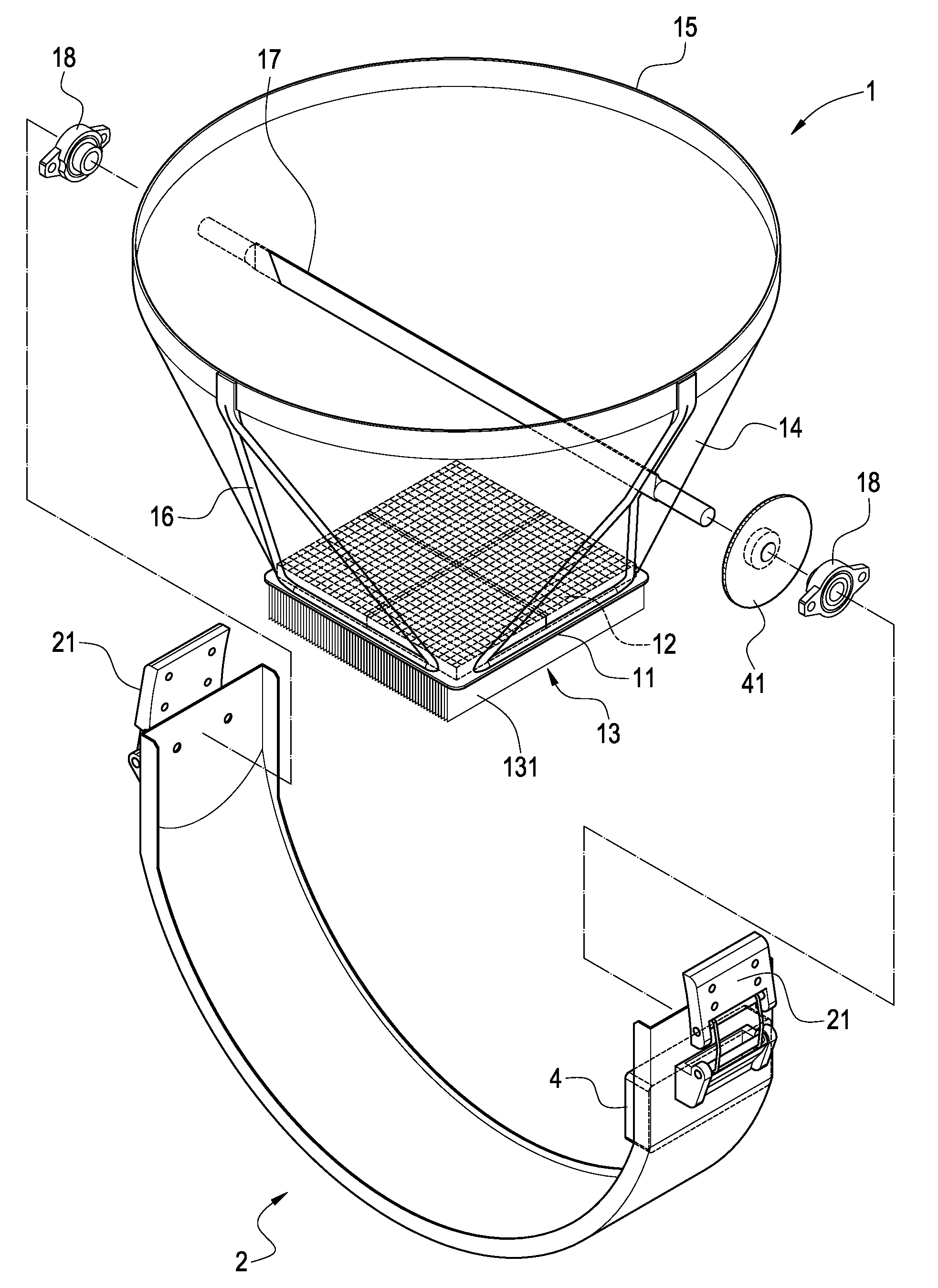
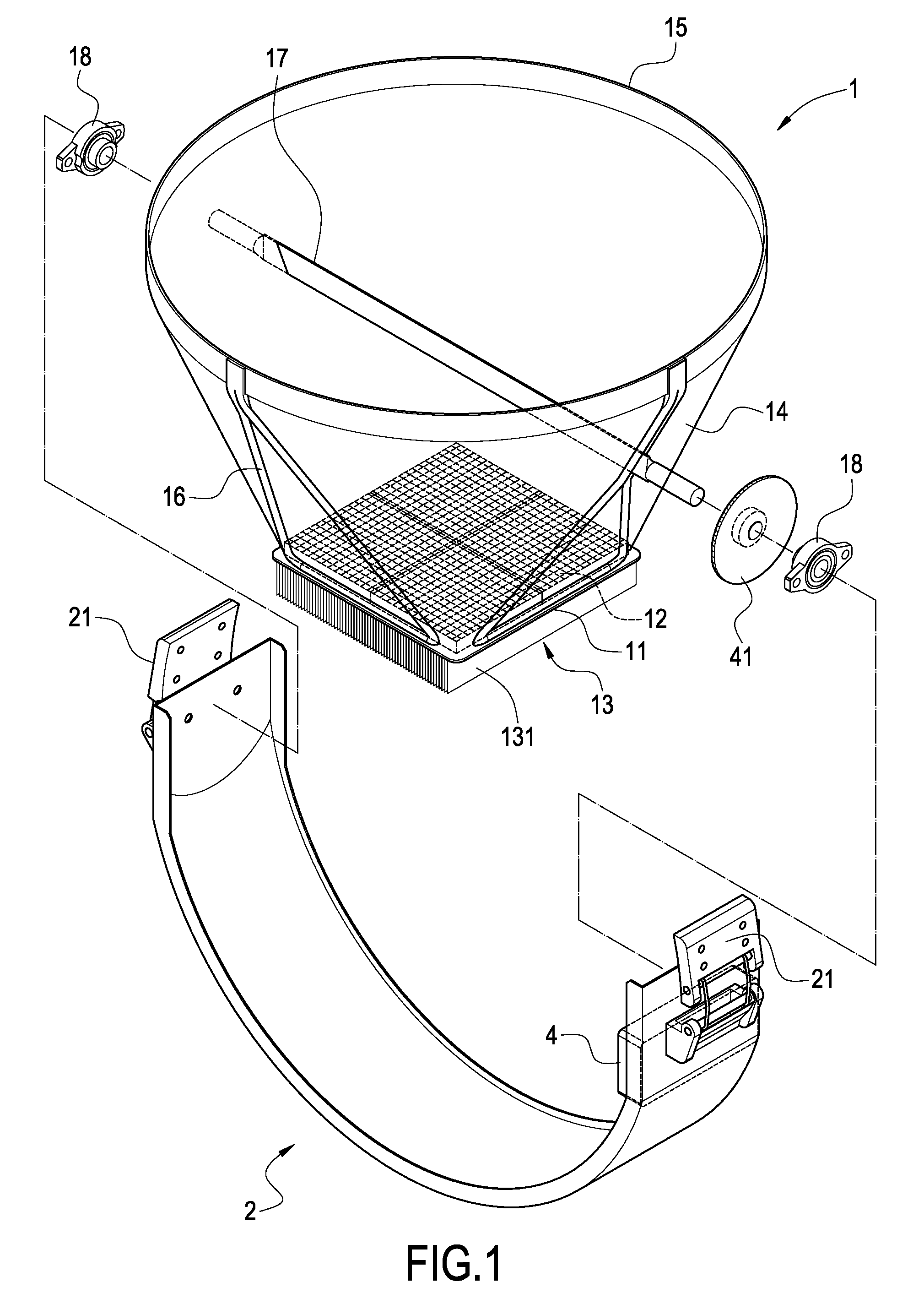
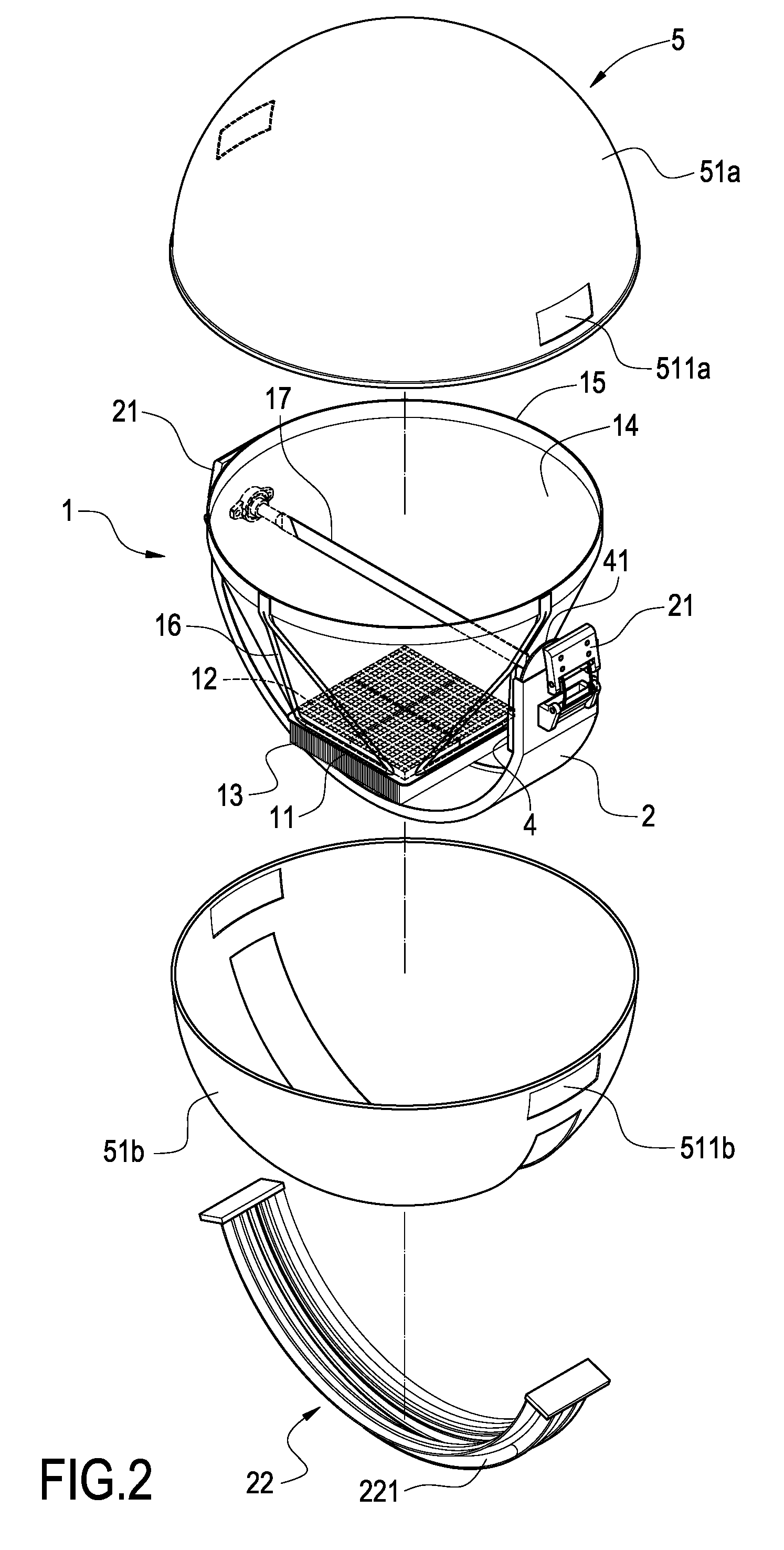
[0023]Referring to FIG. 1 for an exploded view of the present invention, the electric generating structure of the present invention comprises a light collector 1, a retaining base 2 and a base body 3, wherein the light collector 1 further includes a base 11, and an upper panel of the base 11 includes at least one solar panel 12, and the structure of the solar panels 12 of the present embodiment is comprised of four rectangular solar panels 12, and a lower panel of the base 11 includes a heat sink 13, and the heat sink 13 is comprised of a plurality of heat dissipating fins 131 with a high thermal conductivity. Further, the periphery of th...


PUM


Abstract

A solar energy current collection mechanism with a timer and its structure includes a light collector, a retaining base and a base body. The light collector includes a base, a solar panel at the top of the base, a conical light collecting hood around the periphery of the base, a plurality of supporting stands around the light collecting hood and an axle passing though the light collecting hood. The retaining base is disposed under the light collector, and both ends of the retaining base are connected to both ends of the axle. The retaining base includes the timer connected to the axle for driving the light collector to rotate, and the retaining base is disposed on a base body, and the base body includes a control unit and a battery unit electrically connected to a solar panel for controlling and storing the electric power produced by the solar panel.

Description

BACKGROUND OF THE INVENTION[0001]1. Field of the Invention[0002]The present invention relates to an electric generating mechanism, and more particularly to a current collection mechanism that generates electricity by solar energy.[0003]2. Description of Prior Art[0004]Electric power supply has become an indispensable part of our life, and various different electric appliances require electric power for the operation to fulfill our needs, but a great deal of resources is abused. With the increasing population, the usable resources become insufficient, and we have to think over the problem thoroughly again and find other feasible alternate energy source, and solar energy is one of these alternate energy sources.[0005]Solar energy is a pollution-free inexhaustible energy source, and thus solar energy has become one of the most important subjects for research. In the past, most solar energy current collectors are of the fixed type that exposes a solar panel with a large area under sunli...

Claims


Application Information

Patent Timeline
Patent Type & Authority Applications(United States)
IPC IPC(8): G01J1/20
CPCF24J2/05F24J2/5424F24J2002/4663F24J2002/5475H01L31/052H01L31/0547Y02E10/47Y02E10/52H02S20/00H01L31/0543Y02E10/44H02S20/30F24S30/455F24S2025/6003F24S2030/14F24S10/40
Inventor WANG, CHIN-WEN
Owner LEADER KEY
Learn More