Antisqueezed Light Generator
- Summary
- Abstract
- Description
- Claims
- Application Information
AI Technical Summary
Benefits of technology
Problems solved by technology
Method used
Image
Examples
first embodiment
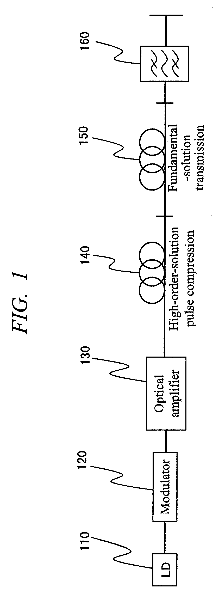
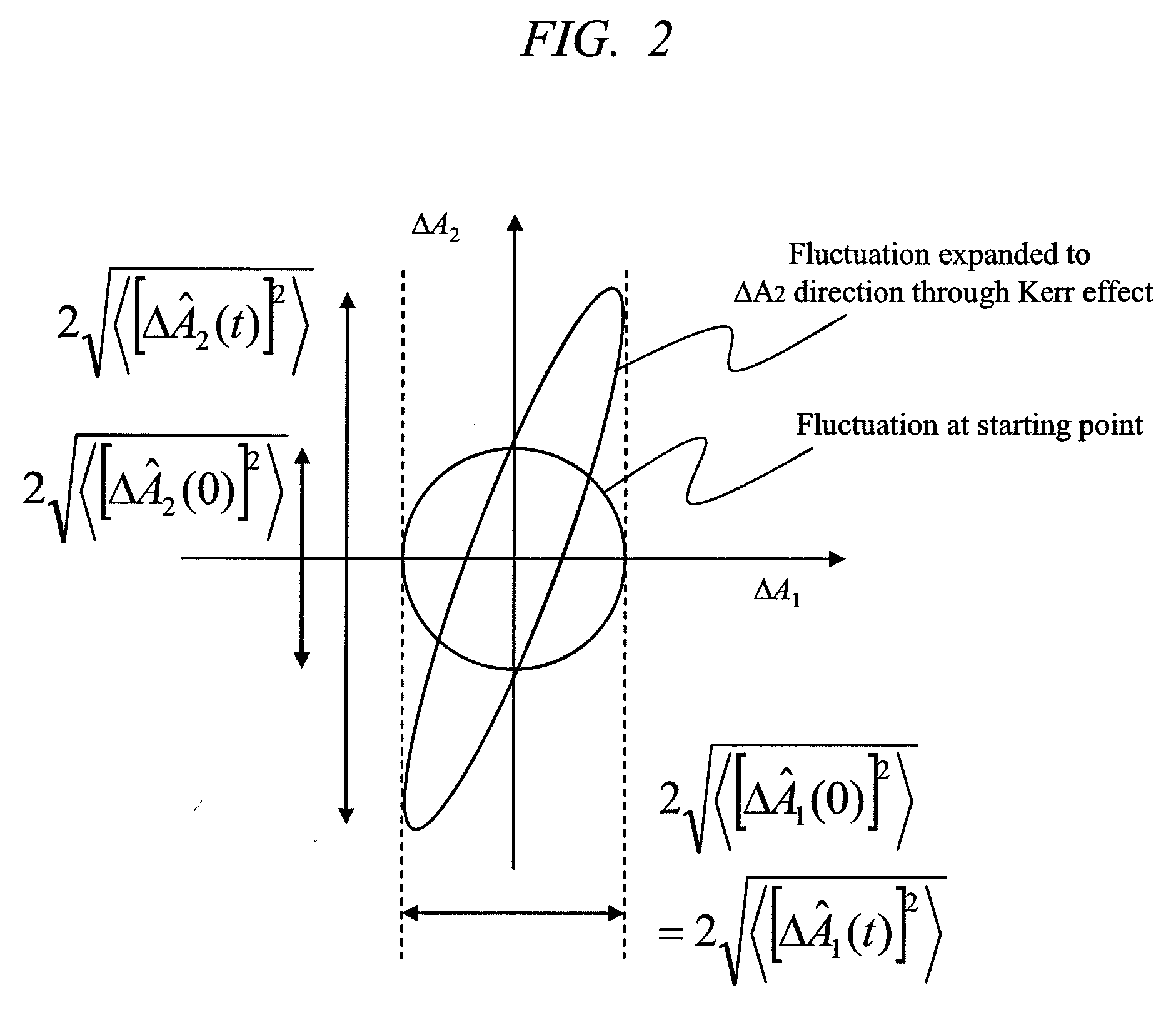
[0030]FIG. 1 is a block diagram which shows one embodiment of the present invention. Output light from a cw LD 110 is converted into pulsed light by an intensity modulator 120, amplified by an optical amplifier 130, and transmitted to a single-mode fiber 140 which exhibits negative group-velocity dispersion at the operating wavelength of the LD 110. The pulsed light transmitted in the optical fiber is subject to a wavelength-dependent dispersion specific to the fiber and the light intensity-dependent Kerr effect. At an appropriate light intensity, the dispersion effect and the Kerr effect are balanced and the pulsed light is transmitted in the fiber with the pulse waveform being maintained. This is a state called the fundamental soliton. When the light intensity is increased from this soliton condition, a high-order soliton state is generated and a pulse width is varied in a period called the soliton period. If the transmission in the fiber 140 is terminated at a spot where the puls...
second embodiment
[0068]Single mode fibers are basically formed circularly symmetric, but has slight birefringence caused by strain, twist, or bend. Because of this birefringence, the polarization of the transmitted light is varied, whereby the effective Kerr effect is slightly changed. If a polarization controller 141 is installed ahead of the input of the fiber 140 as shown in FIG. 6, it is possible to control the effective Kerr effect and to obtain the optimum condition for high-order soliton compression. Similarly, if a polarization controller 151 is installed ahead of the input of the fiber 150, it is possible to control the effective Kerr effect in the fiber 150 and to get the optimum condition in generating the antisqueezed light.
third embodiment
[0069]In the first and second embodiments, one-directional configurations are adopted and they are advantageous from a viewpoint of their simple configuration. However, for the fiber 150, the length of 10 to several tens km is typically required, which is rather uneconomical. FIG. 7 shows a round-trip transmission configuration for the fiber 150. The configuration up to the fiber 140 is the same as that of the first Embodiment. After the fiber 140, the light first passes an isolator 145. This is needed because slight returned light is present in the round-trip configuration. Next, the light is controlled to linearly polarized light by a polarization controller 146 and passes a polarizing beam splitter 147. If the transmission line from the LD 110 to the polarizing beam splitter 147 is connected with polarization-maintaining fibers, the polarization controller 146 can be omitted. After passing the polarizing beam splitter 147, the light is transmitted in the fiber 150, is converted i...
PUM
 Abstract
Description
Claims
Application Information
 - R&D
- Intellectual Property
- Life Sciences
- Materials
- Tech Scout
- Unparalleled Data Quality
- Higher Quality Content
- 60% Fewer Hallucinations
Browse by: Latest US Patents, China's latest patents, Technical Efficacy Thesaurus, Application Domain, Technology Topic, Popular Technical Reports.
© 2025 PatSnap. All rights reserved.Legal|Privacy policy|Modern Slavery Act Transparency Statement|Sitemap|About US| Contact US: help@patsnap.com


