Wake vortex detection and reporting system

Inactive Publication Date: 2012-03-13
DTN LLC
View PDF21 Cites 48 Cited by
  • Summary
  • Abstract
  • Description
  • Claims
  • Application Information

AI Technical Summary

Benefits of technology

[0016]Thus, a system that combines environmental conditions information with aircraft specific information and produces a simplified display map showing any environmental conditions that are relevant to a particular aircraft, improves pilot awareness, reduces the workload on the pilot, and improves the safety level to the aircraft, the pilot, and any passengers and / or cargo onboard.
[0017]Thus, in contrast to the example of merely displaying environmental conditions information described above, this invention allows the pilot to look at the display map without having to determine, for example, which color-coded pie shapes represent wind variations that are intense enough to adversely affect his or her particular aircraft. To the contrary, the display map of this invention only displays environmental conditions that exceed a determined threshold and can actually affect the pilot's particular aircraft. Thus, in contrast to the example described above, the display map of this invention will only show areas of wind variation that are intense enough to adversely affect the pilot's aircraft.
[0025]When the vehicle is, for example, an automotive vehicle, the environmental conditions information may include, for example, weather conditions, wind speed, wind direction, accumulated precipitation information, road conditions, grade of terrain traversed, or the like. It should also be appreciated that the environmental conditions information is displayed relative to each particular automotive vehicle's attributes, such as, for example, two wheel or four wheel drive, gross vehicle weight, speed, height, center of gravity, or the like. If, for example, the vehicle is a tractor-trailer, the display may include wind speed and direction information so that a driver can avoid areas of crosswinds that are strong enough to tip the vehicle or force the vehicle off a road.
[0033]This invention separately provides apparatuses, systems, and methods that optimize a course around various environmental conditions based on specific criteria, such as, for example, best fuel economy, most comfortable ride, fastest traverse of a particular region, and / or changing configuration of the vehicle.
[0035]This invention separately provides apparatuses, systems, and methods that provide the user with improved situational awareness of hazards to the user's specific vehicle.
[0036]This invention separately provides apparatuses, systems, and methods that improve safety by reducing the impact of adverse environment conditions on a specific vehicle.

Problems solved by technology

Performance limitations can include, for example, the aircraft's maximum speed and Mach number, buffet speed, operational ceiling, maximum weight, center of gravity, as well as the structural and mechanical limitations of the aircraft.
Furthermore, a private jet, with an excess of available power, can fly in conditions that a small, single engine, propeller-driven aircraft cannot.
However, both large and small aircraft alike can be catastrophically affected by, for example, a lightning strike.

Method used


Image

  • Wake vortex detection and reporting system
  • Wake vortex detection and reporting system
  • Wake vortex detection and reporting system

Examples


Embodiment Construction

[0054]For simplicity and clarification, the operating principles, design factors, and layout of the environmental conditions display systems, methods, and apparatuses according to this invention are explained with reference to various exemplary embodiments of environmental conditions display systems, methods, and apparatuses according to this invention. The basic explanation of the operation of the environmental conditions display systems, methods, and apparatuses is applicable for the understanding and design of the constituent components employed in the environmental conditions display systems, methods, and apparatuses of this invention.

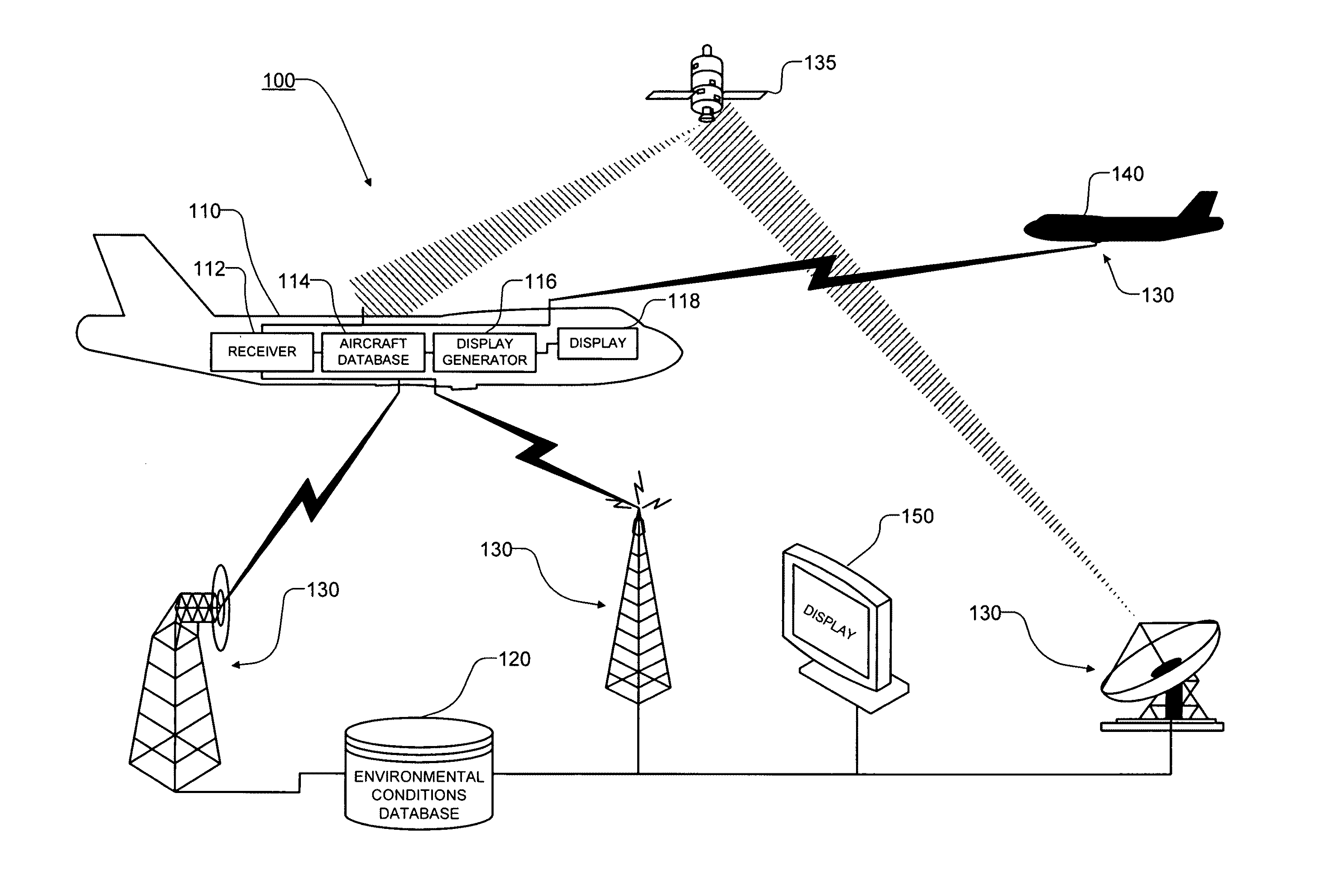
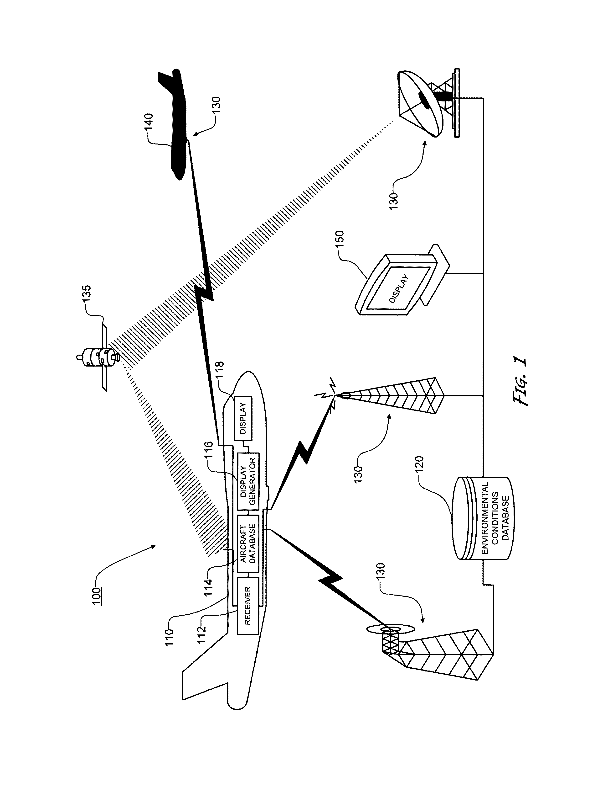
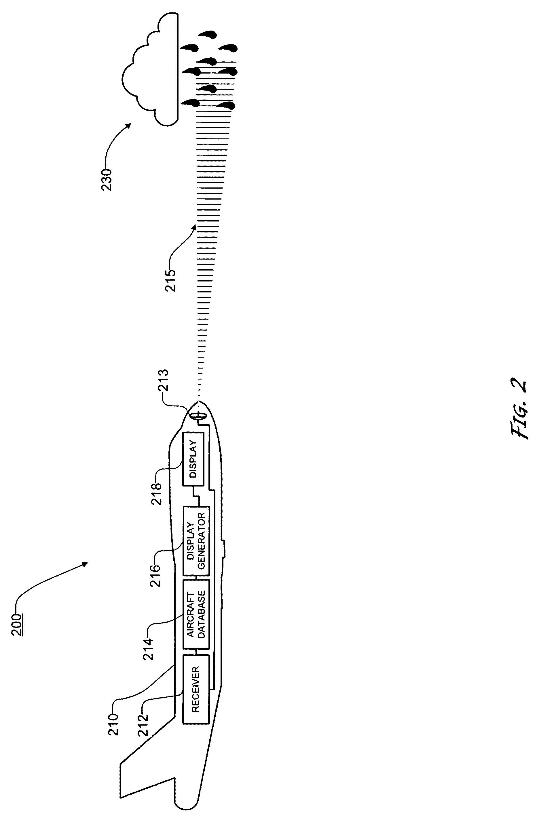
[0055]Furthermore, it should be appreciated that, for simplicity and clarification, the embodiments of this invention will be described with reference to the environmental conditions display systems, methods, and apparatuses as they operate in an aircraft. Alternatively, the systems, methods, and apparatuses of this invention can be implemented in ...


PUM


Abstract

A method for estimating the effect of environmental conditions on an aircraft, including measuring the motions of an aircraft; estimating the expected motions of the aircraft, wherein the expected motions of the aircraft are estimated using information regarding the aircraft's control inputs and / or control surface positions; and estimating, based on the measured motions of the aircraft and the expected motions of the aircraft, the forces exerted on the aircraft by the environmental conditions, wherein the forces are estimated based on a difference between the measured motions of the aircraft and expected motions of the aircraft.

Description

CROSS-REFERENCE TO RELATED APPLICATIONS[0001]This is a Continuation-In-Part of U.S. patent application Ser. No. 11 / 475,670, filed Jun. 27, 2006, now U.S. Pat. No. 7,471,995 which is a Continuation-In-Part of U.S. patent application Ser. No. 11 / 122,909, filed May 5, 2005, now U.S. Pat. No. 7,463,955 which is a Continuation-In-Part of U.S. patent application Ser. No. 10 / 408,024, filed Apr. 4, 2003, and issued Jul. 12, 2005, as U.S. Pat. No. 6,917,860, which is a Continuation-In-Part of U.S. patent application Ser. No. 10 / 083,840, filed Feb. 27, 2002, and issued Nov. 18, 2003, as U.S. Pat. No. 6,650,972, which is a Continuation-In-Part of U.S. patent application Ser. No. 09 / 583,042, filed May 26, 2000, and issued Apr. 30, 2002, as U.S. Pat. No. 6,381,538, the disclosures of which are incorporated herein by reference.BACKGROUND OF THE INVENTION[0002]1. Field of the Invention[0003]This invention relates generally to the transmission, receipt, processing, and presentation of vehicle speci...

Claims


Application Information

Patent Timeline
IPC IPC(8): G01C23/00
CPCG01C23/00G08G5/0008G08G5/0013G08G5/0021G08G5/0052G08G5/0091
Inventor ROBINSON, PAUL A.
Owner DTN LLC
Why Eureka
Try Eureka