
Solid-state image-pickup device and method of processing signal of solid-state image-pickup device

a solid-state image and pick-up device technology, applied in the direction of color television details, television systems, radio control devices, etc., can solve the problem of making an unnatural impression on a viewer, and achieve the effect of reducing circuit scale, grading a signal output after the addition, and fluctuating the signal output of the adder

Inactive Publication Date: 2007-12-27
SONY CORP
View PDF3 Cites 5 Cited by
  • Summary
  • Abstract
  • Description
  • Claims
  • Application Information

AI Technical Summary

Benefits of technology

[0012]The above-described solid-state image-pickup device includes the adder configured to add the randomly distributed signals to the at least one step-like discrete gradation signal output from the multiplier. Therefore, the gradation of a signal output from the adder fluctuates smoothly.
[0014]The above-described solid-state image-pickup device includes the bit-insertion circuit configured to insert the randomly distributed signals into the at least one step-like discrete gradation signal output from the bit-shift circuit. Therefore, the gradation of a signal output from the bit-insertion circuit fluctuates smoothly.
[0016]According to the above-described method, the randomly distributed signals generated by using the sensor signal, as the seed, are added to the signal corresponding to the step-like discrete gradation that occurs due to the digital-gain processing. Therefore, the gradation of a signal output after the addition fluctuates smoothly.
[0017]According to the above-described solid-state image-pickup device, the randomly distributed signals are added to the at least one step-like discrete gradation signal output from the multiplier, so that the gradation of the signal output from the adder fluctuates smoothly. Subsequently, a gradation part that fluctuates gently by nature looks natural.
[0018]According to the above-described solid-state image-pickup device, the randomly distributed signals are inserted into the at least one step-like discrete gradation signal output from the bit-shift circuit. Subsequently, the gradation of the signal output from the bit-insertion circuit fluctuates smoothly, so that the gradation part that fluctuates gently by nature looks natural. Further, since specifications of the digital-gain processing are limited, the bit-shift circuit is used in place of the multiplier and the bit-insertion circuit is used in place of the adder. Subsequently, the circuit scale can be significantly reduced.
[0019]According the above-described method of processing the signal of the solid-state image-pickup device, the randomly distributed signals generated by using the sensor signal, as the seed, are added to the at least one signal generated through the digital-gain processing, the signal corresponding to the step-like discrete gradation. Therefore, the gradation of the signal output after the addition is performed fluctuates smoothly, so that the gradation part that fluctuates gently by nature looks natural.

Problems solved by technology

As a result, when the sensor signal is displayed, as an image, a gradation part that should fluctuate gently by nature looks like steps, which makes an unnatural impression on a viewer.

Method used


Image

  • Solid-state image-pickup device and method of processing signal of solid-state image-pickup device
  • Solid-state image-pickup device and method of processing signal of solid-state image-pickup device
  • Solid-state image-pickup device and method of processing signal of solid-state image-pickup device

Examples


first embodiment

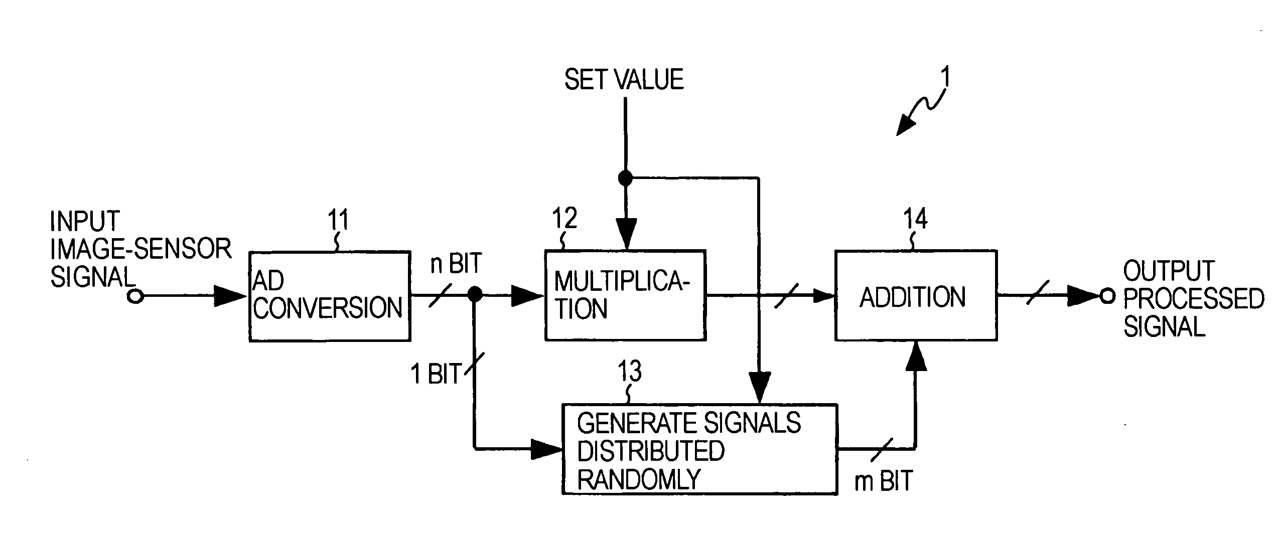
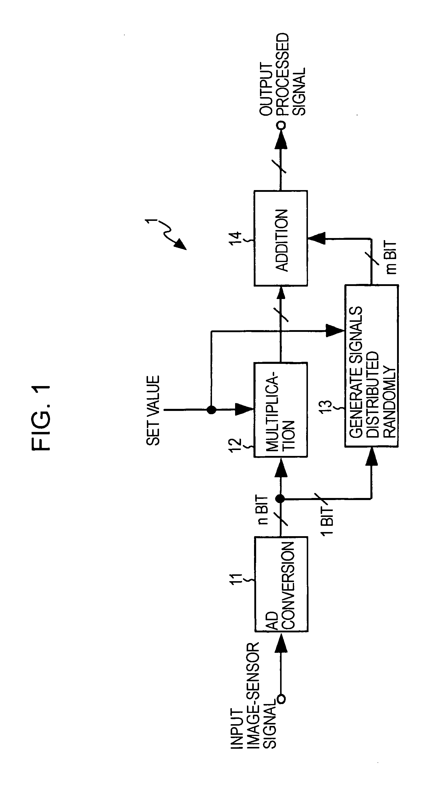
[0027]FIG. 1 is a block diagram illustrating a solid-state-image-pickup device 1 and a method of driving the solid-state-image-pickup device 1 according to the present invention. FIG. 1 shows a digital-gain-processing part of the solid-state image-pickup device 1 including an image sensor or the like.

[0028]As shown in FIG. 1, the solid-state image-pickup device 1 includes an analog-to-digital converter (hereinafter referred to as AD converter) 11 provided, so as to convert an analog-sensor signal into an n-bit digital signal, the analog-sensor signal being read by the image sensor driven in a predetermined manner. Subsequently, an analog-sensor signal input to the AD converter 11 due to an input image-sensor signal is converted into a digital signal and output, as a sensor signal.

[0029]Further, the solid-state image-pickup device 1 includes a multiplier 12 configured to digitally multiply the sensor signal output from the AD converter 11 by an input fixed value. Still further, the s...

second embodiment

[0040]FIG. 5 is a block diagram illustrating a solid-state image-pickup device 2 and a method of driving the solid-state image-pickup device 2 according to the present invention. FIG. 5 shows a digital-gain-processing part of the solid-state image-pickup device 2 including an image sensor or the like.

[0041]As shown in FIG. 5, the solid-state image-pickup device 2 includes the AD converter 11 provided, so as to convert an analog-sensor signal into the n-bit digital signal, the analog-sensor signal being read by the image sensor driven in a predetermined manner. Subsequently, an analog-sensor signal input to the AD converter 11 due to the image-sensor-signal input is converted into the digital signal and output, as the sensor signal.

[0042]Further, the solid-state image-pickup device 2 includes a bit-shift circuit 31 configured to perform bit sifting for the sensor signal output from the AD converter 11 in the most-significant-bit (MSB) direction and insert zero onto the least-signific...


PUM


Abstract

A solid-state image-pickup device including a multiplier configured to perform digital-gain processing for a sensor signal output from an analog-to-digital converter configured to convert an analog signal of an image sensor into a digital signal is provided. The solid-state image-pickup device includes a signal generator configured to generate randomly distributed signals, and an adder configured to add the randomly distributed signals to at least one signal with step-like discrete gradation, the signal being output from the multiplier.

Description

CROSS REFERENCES TO RELATED APPLICATIONS[0001]The present invention contains subject matter related to Japanese Patent Application JP 2006-175013 filed in the Japanese Patent Office on Jun. 26, 2006, the entire contents of which are incorporated herein by reference.BACKGROUND OF THE INVENTION[0002]1. Field of the Invention[0003]The present invention relates to a solid-state image-pickup device and a method of processing a signal of the solid-state image-pickup device.[0004]2. Description of the Related Art[0005]Some of known image sensors often have the function of performing digital-gain processing by multiplying a sensor signal that had been subjected to analog-to-digital conversion (hereinafter referred to as AD conversion) by a given set value and the sensor signal. According to the digital-gain processing, multiplication is performed for an input sensor signal in a digital manner and information about the multiplication result is output. Namely, operations performed, so as to a...

Claims


Application Information

Patent Timeline
IPC IPC(8): H04N1/04H01L27/146H04N5/335H04N5/357H04N5/369H04N5/378
CPCH04N5/243H04N5/357H04N5/335H04N23/76H04N25/00H04N25/60
Inventor KATO, AKIHIKOFUKUSHIMA, NORIYUKI
Owner SONY CORP
Learn More