
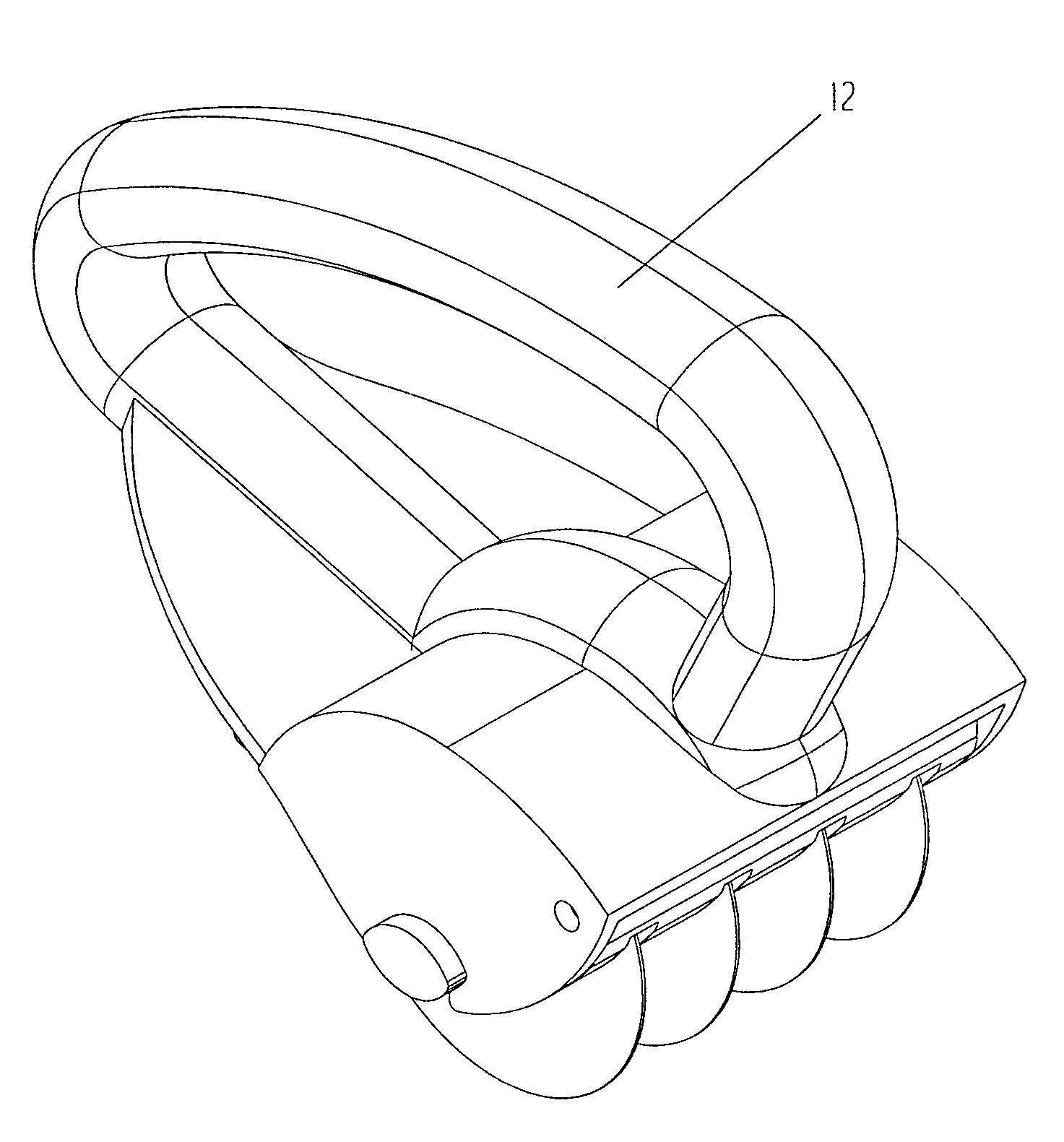
Rotating food-processing knife with detachable multi blade axis

a multi-blade, rotating technology, applied in metal-working hand tools, metal working apparatus, manufacturing tools, etc., can solve the problems achieve the effect of reducing premature user fatigue and unnecessary burden, maximizing force transfer, and quick and effortless manner

Inactive Publication Date: 2007-12-27
BELTRAN ROBERTO
View PDF13 Cites 16 Cited by
  • Summary
  • Abstract
  • Description
  • Claims
  • Application Information

AI Technical Summary

Benefits of technology

[0009]Considering the above problems of existing designs, the object of the present invention is to provide a food processing knife with the capability to slit or chop large amounts of hot of the grill meat and other food stuffs in a rapid and effortless manner. This artifact must enable the user to perform simultaneous cuts per stroke, eliminate the need for an extra utensil such as a fork to hold the meat when processing and maximize force transfer to decrease premature user fatigue and unnecessary burden.
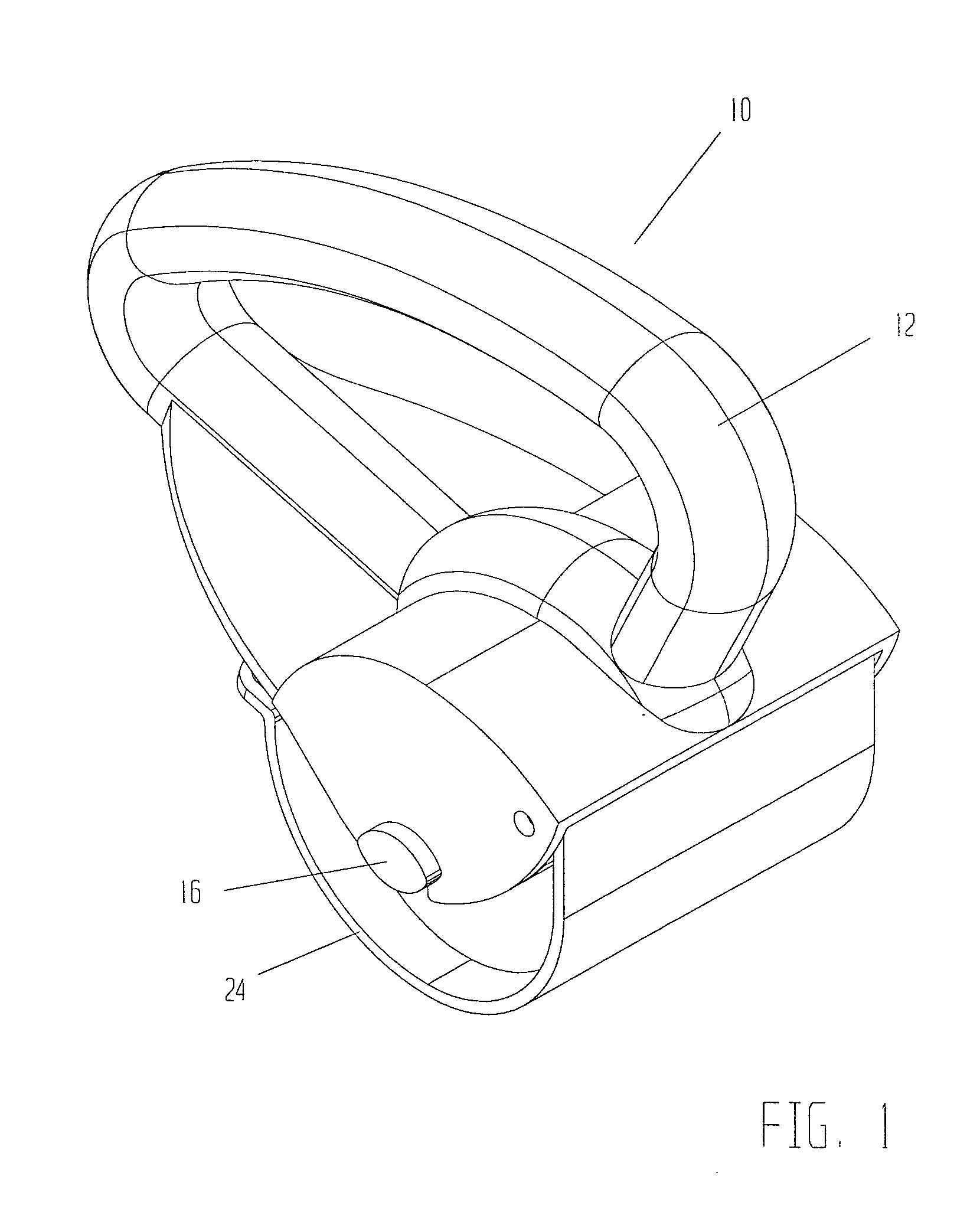
[0010]In order to achieve the stated design objective the present invention has a closed loop rigid handle with integrated blade axis housing, protective guards, and assembly provisions for a rotating multi circular blade axis, a swiveling blade axis holder, a blade axis holder lock and a blade axis safety cover. The handle is geometrically fitted such that the user's hand grip point is located right over the blade rotating axis thus forming a full vertical force transfer plane between the user's hand and blade axis. This configuration maximizes force transfer efficiency and consequently decreases the required down force (vertical component) to cut into the meat thus diminishing premature user fatigue.
[0011]The blade axis is composed of equidistant circular blades configured in a parallel array along a symmetry axis. The blades are held in place by spacer bushings that are compressed by locking nuts located at opposite ends. The locking nuts and spacer bushings encapsulate a stiffener rod which prevents the blade axis assembly to flex beyond a given design distance when a maximum operating force is applied to it. This multi bladed configuration enables the user to perform simultaneous cuts per stroke thus decreasing processing time.
[0012]When the blade axis is locked in place it is allowed to freely rotate clockwise or counterclockwise on an axis perpendicular to the cut direction. This particular characteristic permits the user to cut into the meat with a forward and backward motion and since the blade shape is circular the contact section per blade is smaller than conventional straight blades therefore permitting easier blade penetration and eliminating the need for a utensil to prevent grilled meat sliding over the chopping board.
[0013]When slit meat is desired the knife is rolled back and forth with a small increase in the motion direction angle. If chopped meat is preferred the same forward and backward motion is employed with greater angle change in motion direction. This generates multidirectional simultaneous cuts thus chopping the grilled meat rapidly.
[0014]The combination of the above characteristics allows the user to easily process hot of the grill meat in and effortless and rapid manner without suffering from premature fatigue. This allows for several warm meal preparations in a short time period and permits the user to process large meat quantities without the tiring and unpleasant burden associated with such activity when other artifacts are employed.

Problems solved by technology

This configuration maximizes force transfer efficiency and consequently decreases the required down force (vertical component) to cut into the meat thus diminishing premature user fatigue.

Method used


Image

  • Rotating food-processing knife with detachable multi blade axis
  • Rotating food-processing knife with detachable multi blade axis
  • Rotating food-processing knife with detachable multi blade axis

Examples


Embodiment Construction

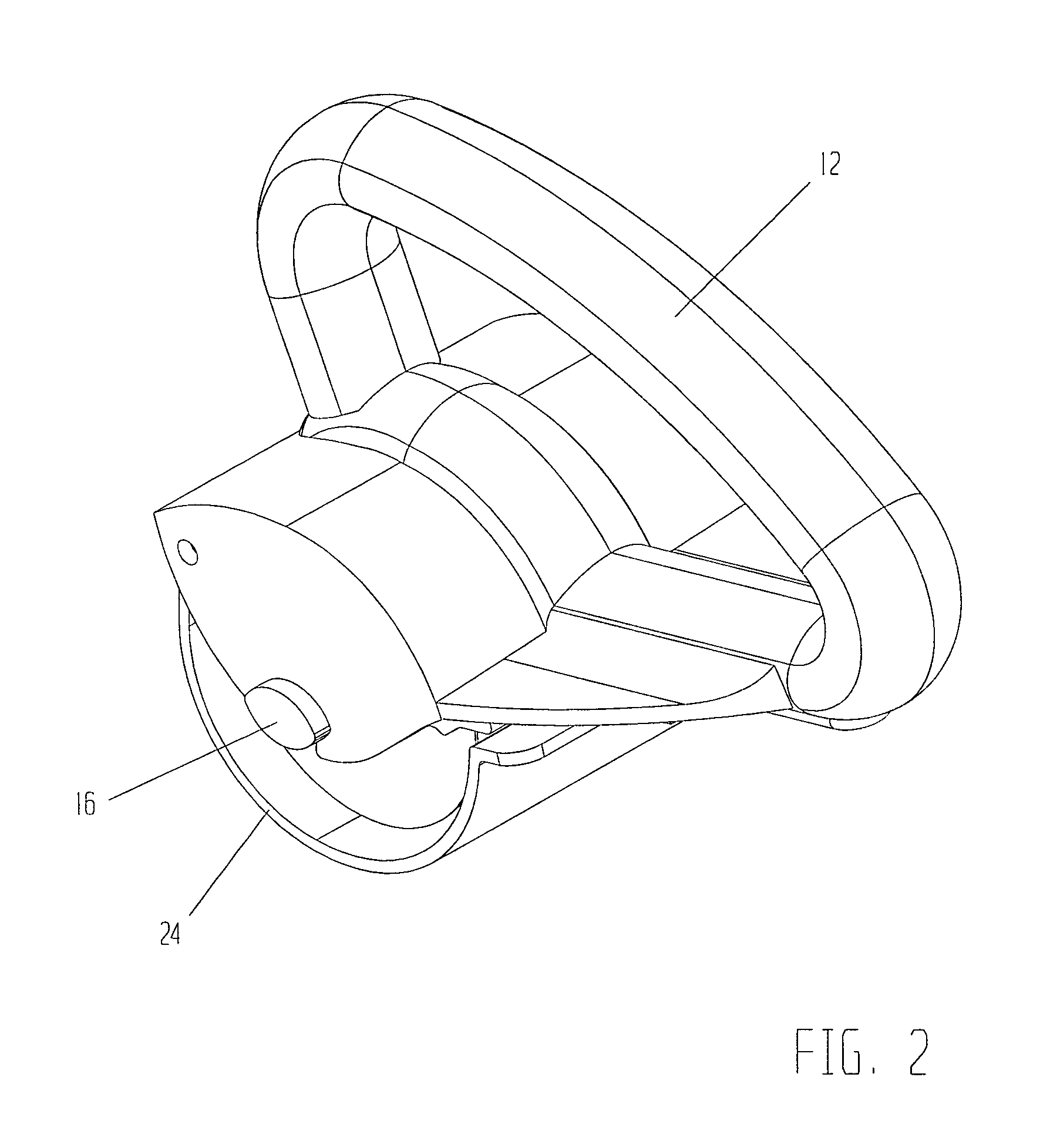
[0035]A rotary food processing knife according to a first embodiment of the present invention is depicted in FIGS. 1 through 19. While the invention will be described in detail herein below with reference to this embodiment, it should be understood that the invention is not limited to the specific constructions or configurations shown in the embodiment. Rather, one skilled in the art will appreciate that a variety of configurations may be implemented in accordance with the present invention.

[0036]Looking first to FIGS. 1, 2, 3, 4, 5, 6, 9 and 10, a rotary circular knife with detachable multi blade axis in accordance with an embodiment of the present invention is depicted generally by the designation 10. Rotary knife 10 includes a rigid trolley 12 defining a cavity 14 configured to partially cover and house a multi circular blade axis 16 thus protecting the user's hand from accidental cuts during operation, and further defining a rectangular passage 18 allocating a blade axis holder ...


PUM


Abstract

A specialty food-processing knife includes a rigid handle, a circular blade axis, a blade axis holder, a blade axis holder lock, and a blade axis safety cover. The handle provides a blade axis upper housing to cut protect the user's hand and is configured with guide grooves, coupling pivot holes, and a guide tunnel. The guide grooves restrict the blade axis movement to a circular motion, the pivot holes allow swiveling of the blade axis holder, and the guide tunnel provides unidirectional motion to the blade axis holder lock. The blade axis is composed of several parallel circular blades, which are held in position by spacer bushings and lock nuts that encapsulate a stiffener rod. The blade axis holder presents a parallel slotted array to prevent food fragments from entering the blade axis housing and allow the axis blades to be partially exposed and rotate freely. The blade axis holder lock includes barriers, which limit the lock to an open or closed position. The blade axis cover has a locating lip that allows coupling with the knife handle.

Description

BACKGROUND OF THE INVENTION[0001]1. Field of the Invention[0002]The present invention relates to food processing knifes, and more particularly to a food processing knife with parallel rotating circular blades.[0003]2. Description of Related Art[0004]When cooking courses, there are some meals that are served on the spot and require hot of the grill meat which must be slit or chopped for course preparation therefore, the cutting operation must be performed at a fast pace to prevent the grilled meat from getting cold and be able to serve several meals simultaneously. Generally, this cutting action is carried out by employing single bladed knives which require great effort to continuously process large meat quantities in a short time period thus quickly fatiguing the user and presenting an unnecessary burden that is tiring, unpleasant and time consuming.[0005]Fixed blade knives with a single straight blade attached to a wood or plastic handle by means of glue or rivets are commonly used...

Claims


Application Information

Patent Timeline
Patent Type & Authority Applications(United States)
IPC IPC(8): B26B3/00
CPCB26B25/005B26B5/008
Inventor BELTRAN, ROBERTO
Owner BELTRAN ROBERTO
Learn More