Synthesis gas production method and reactor

Inactive Publication Date: 2007-12-20
STATOIL ASA PETRO SA (NO) +1
View PDF9 Cites 62 Cited by
  • Summary
  • Abstract
  • Description
  • Claims
  • Application Information

AI Technical Summary

Benefits of technology

[0019]By independently controlling the temperature within the catalytic reaction zones, upstream reaction stages can be constructed from less expensive and conventional high temperature alloys where final reaction stages that operate at high temperature can be fabricated from more expensive materials such as an oxide dispersed strengthened metal. This arrangement minimizes the use of the more expensive high temperature materials. In this regard, the oxygen transport membrane elements comprise metallic supports and oxygen transport membrane materials supported by the metallic supports. The metallic supports utilized in the at least the final of the reaction stages from which the synthesis gas stream is discharged can be fabricated from the oxide dispersed strengthened metal. The metallic supports of the oxygen transport membrane elements of at least one of the reaction stages located upstream of the at least the final of the reaction stages are fabricated from a high temperature metallic material that does not constitute the oxide dispersed strengthened metal. Furthermore, a final of the oxygen containing streams fed to the final of the reaction stages can be compressed to reduce pressure differential between the separation zones and the catalytic reactant zones located within the final of the reactant stages. This also will help decrease the use of the more expensive high temperature materials such as oxide dispersed strengthened metals by decreasing the mechanical stresses induced by the pressure differential.
[0021]In order to reduce carbon formation and possible catalyst poisoning, a hydrogen containing stream and a first steam stream can be combined with a portion of a hydrocarbon containing feed to produce a first of the reactant streams. The first of the reactant streams is fed to a first of the catalytic reaction zones. A second steam stream is combined with the remaining portion of the hydrocarbon containing gaseous feed to produce the remainder of the reactant streams fed to the catalytic reaction zones located downstream of the first of the reaction stages. The steam to carbon ratio can be controlled within the first of the catalytic reaction zones to help prevent solid carbon formation by metering the first steam stream. The hydrogen containing stream can be made up of recycled Fisher-Tropsch tail gas.
[0022]The foregoing allows the reactor to operate with a high steam to carbon ratio, or with an abundance of hydrogen present throughout the reactor so as to avoid carbon lay down. Carbon is laid down by various reactions including the decomposition of methane to carbon and hydrogen. The carbon can be removed by reaction of the carbon with hydrogen and with steam to produce carbon monoxide and additional hydrogen. These reactions, as well as other reactions that occur between carbon monoxide, carbon dioxide, carbon, methane, steam and hydrogen, are essentially equilibrium reactions. As such, the reactions can be driven in the reverse direction by maintaining a sufficient partial pressure of steam and / or hydrogen in all of the reaction stages. If a hydrocarbon containing reactant is added in stages to a fixed amount of steam, these ratios can be kept on the safe side, namely, away from carbon lay down. In this regard, initially the steam to carbon ratio is high as only a portion of the hydrocarbons to be reacted is added to all of the steam. As the reactions proceed, hydrogen is manufactured, so when additional tranches of feed stock are added to the reaction stages, which drives down the steam to total carbon ratio, the presence of hydrogen helps protect against carbon lay down. Consequently the addition of hydrocarbons can be arranged in such manner that the process stream remains out of the carbon lay down region.

Problems solved by technology

However, at high operational temperatures, oxygen transport materials and supporting materials that are used to support the oxygen transport membrane can, over time, degrade and even fail by known creep mechanisms of failure.
Compounding this problem is that the oxygen flux developed by the oxygen transport membrane is dependent upon temperature.
This creates a problem in either partial oxidation reactors or autothermal reforming reactors.
This creates an uncontrolled temperature rise in the oxygen transport membrane material by consequential increases in oxygen flux and hydrocarbon consumption.
This uncontrolled temperature rise is referred to as thermal run-away to also cause failure at the oxygen transport membrane.
In autothermal reactors a further problem is that as steam methane reforming reaction proceed along the length of the reactor, the reactants become evermore dilute to reduce the degree of synthesis gas conversion below that which is theoretically possible.
A still further problem is that at the high operating temperatures of reactors incorporating oxygen transport membranes, that higher order hydrocarbons tend to decompose and thereby form carbon deposits on catalysts employed within the reactor.
Such deposits will eventually destroy the catalyst.
The disadvantage is that the final stage utilizes an oxygen-fired autothermal reformer or an air fired steam reformer.
The problem of employing staged reaction as described above is that a downstream conventional reactor is required in order to complete the conversion of the hydrocarbons to synthesis gas.
The use of oxide dispersed strengthened metals has the drawback of expense.
The use of prereformers to control carbon formation introduce expense and complexity to the facility.

Method used


Image

  • Synthesis gas production method and reactor
  • Synthesis gas production method and reactor
  • Synthesis gas production method and reactor

Examples


Embodiment Construction

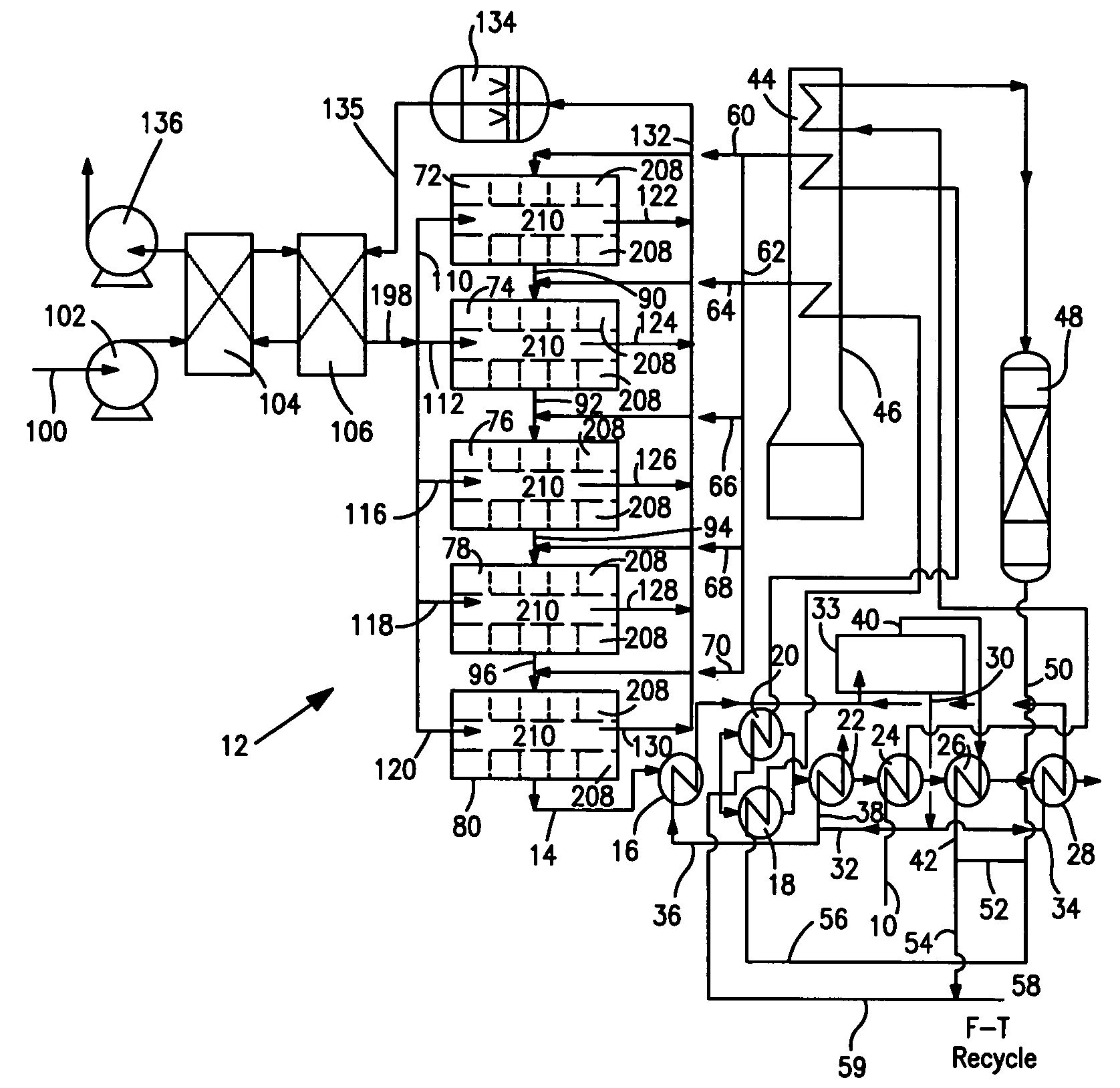
[0038]With reference to FIG. 1, a process flow diagram is illustrated for producing hydrogen from a hydrocarbon containing gaseous feed which can be a natural gas feed stream 10. Natural gas feed stream 10 is processed within a reactor 12 to produce a synthesis gas product stream 14.

[0039]Reactor 12 is employed in a heat transfer and steam generation environment of a type that is employed in connection with conventional steam methane reformers and autothermal reformers. In this regard, synthesis gas product stream 14 is cooled by passage through waste heat boiler 16, mixed feed heaters 18 and 20, a waste heat boiler 22, a natural gas preheater 24, a super heater 26 and a waste heat boiler 28. Steam stream 30 is divided into subsidiary steam streams 32 and 34. Subsidiary steam stream 32 is further divided into portions 36 and 38. Portion 38 passes through waste heat boiler 22 for export and portion 36 passes waste heat boiler 16 and is returned to steam drum 33. Subsidiary steam stre...


PUM

PropertyMeasurementUnit
Temperatureaaaaaaaaaa
Fractionaaaaaaaaaa

Abstract

A method of producing a synthesis gas from a hydrocarbon containing gaseous feed in which the hydrocarbon containing gaseous feed is reacted in an autothermal reactor having separated reaction stages in which partial oxidation and steam methane reforming reactions occur. Each of the reaction stages has alternating separation zones and catalytic reaction zones. Oxygen separated by oxygen ion transport in the separation zone supports the partial oxidation reactions occurring in the catalytic reaction zones. Reactants are separately metered to the reaction stages to control temperatures within the reaction stages so that use of expensive high temperature materials is confined to one or more final reaction stages. Reaction stages can incorporate perforated planar members with regions of oxygen ion transport membrane material in registry with such perforated regions form the separation zones and the catalytic reaction zones.

Description

U.S. GOVERNMENTAL INTEREST[0001]This invention was made with United States Government support under Cooperative Agreement number DE-FC26-01NT41096 awarded by the U.S. Department of Energy, National Energy Technology Laboratory. The United States Government has certain rights in this invention.FIELD OF THE INVENTION[0002]The present invention relates to a method and reactor for producing a synthesis gas product from a hydrocarbon containing gaseous feed in which reactant streams comprising the hydrocarbon containing gaseous feed and steam are subjected to partial oxidation reactions and steam methane reforming reactions within reaction stages of a reactor employing oxygen transport membrane elements to produce oxygen to support the partial oxidation reactions. More particularly, the present invention relates to such a method and reactor in which the reactant streams are metered to each of the reactors to control operational temperatures to minimize the use of high-temperature, expens...

Claims


Application Information

Patent Timeline
IPC IPC(8): C01B3/26B01J12/00
CPCC01B3/382C01B13/0251C01B2203/0244C01B2203/062C01B2203/0844C01B2203/1258C01B2210/0046C01B2203/141C01B2203/142C01B2203/143C01B2203/1614C01B2203/169C01B2203/82C01B2203/127
Inventor HEMMINGS, JOHN WILLIAMBONNELL, LEOROBINSON, EARL T.
Owner STATOIL ASA PETRO SA (NO)
Why Eureka
Try Eureka