Wide Viewing Angle Ocular Fundus Blood Flow Imaging Device

a wide viewing angle and imaging device technology, applied in the field of wide viewing angle ocular fundus blood flow imaging device, can solve the problems of easy errors in reading blood flow value, difficult stare, complicated operation, etc., to reduce the amount of laser bombardment, prevent intrusion, and reduce the laser output

Active Publication Date: 2007-12-20
NAT UNIV CORP KYUSHU INST OF TECH (JP)
View PDF2 Cites 4 Cited by
  • Summary
  • Abstract
  • Description
  • Claims
  • Application Information

AI Technical Summary

Benefits of technology

[0024] The invention related to Claim 18 is the wide viewing angle ocular fundus blood flow imaging device according to any one of Claims 1 to 17, wherein the device has incorporated thereinto a function for retrieving as a signal an exposure timing of the above-mentioned 2-dimensional image sensor, irradiating the ocular fundus with laser only for the time for which each element of this sensor is exposed, and reducing the laser output for the time other than the above, thus reducing the amount of laser bombardment that the ocular fundus receives.
[0025] The invention related to Claim 19 is the wide viewing angle ocular fundus blood flow imaging device according to any one of Claims 1 to 18, wherein an emergent laser optical system is inserted between the subject's eye and an objective lens for observation of the ocular fundus so as to prevent intrusion of a specular reflection component of the laser spot into the blood flow image.
[0026] The invention related to Claim 20 is the wide viewing angle ocular fundus blood flow imaging device according to any one of Claims 1 to 19, wherein by changing the fixation target position during measurement of the blood flow, the influence of seams between a plurality of laser spots is prevented from appearing on the blood flow map.

Problems solved by technology

However, in the conventional device, since the laser spot on the ocular fundus is only on the order of a 3 mm square, the measurement region is limited, and in order to obtain data for blood flow over a wide area it is necessary to carry out measurement many times while changing the measurement position and combine these maps to give a large blood flow map, thus making the operation very complicated.
Furthermore, for an actual patient, it is difficult to stare at one point because of impaired vision; during measurement the line of sight often moves (fixation movement), and when the measurement position deviates due to fixation movement, errors in reading a blood flow value easily occur, which is a problem.
However, since a granular structure due to laser interference remains in the provisional blood flow map, when calculating relative positions between maps, a statistical error corresponding to the granular size occurs.
That is, as long as an image captured by irradiating the ocular fundus with a laser is used, there is a limit to the performance in tracking fixation movement.

Method used


Image

  • Wide Viewing Angle Ocular Fundus Blood Flow Imaging Device
  • Wide Viewing Angle Ocular Fundus Blood Flow Imaging Device
  • Wide Viewing Angle Ocular Fundus Blood Flow Imaging Device

Examples


Embodiment Construction

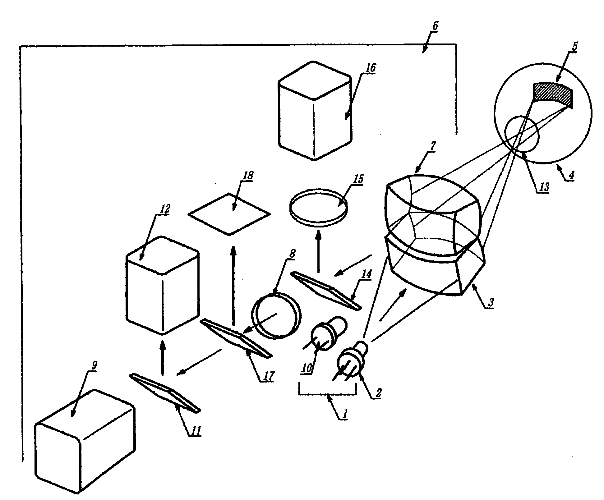
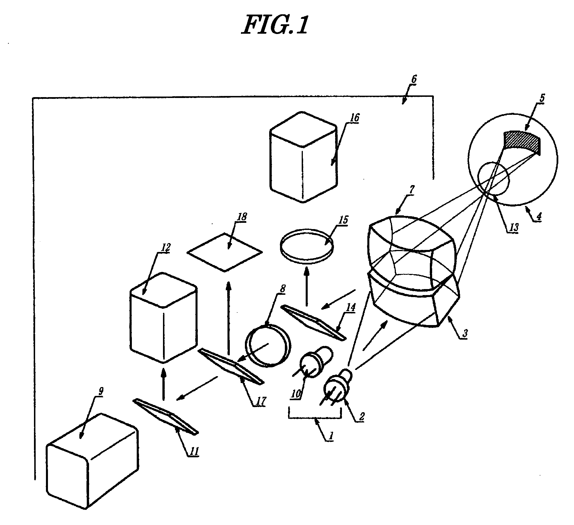
[0040] The present invention comprises a projection system in which a laser beam is turned into a rectangular spot on the ocular fundus and an observation system in which this rectangular spot is imaged on an image sensor placed on the corresponding image plane, and the rectangular spot referred to in the present invention (the inventions of all Claims) includes a horizontally long or vertically long elliptical shape and a semicircular spot. One, or two or more beams may be used as the laser beam, but one or two beams are preferable in terms of simplicity.

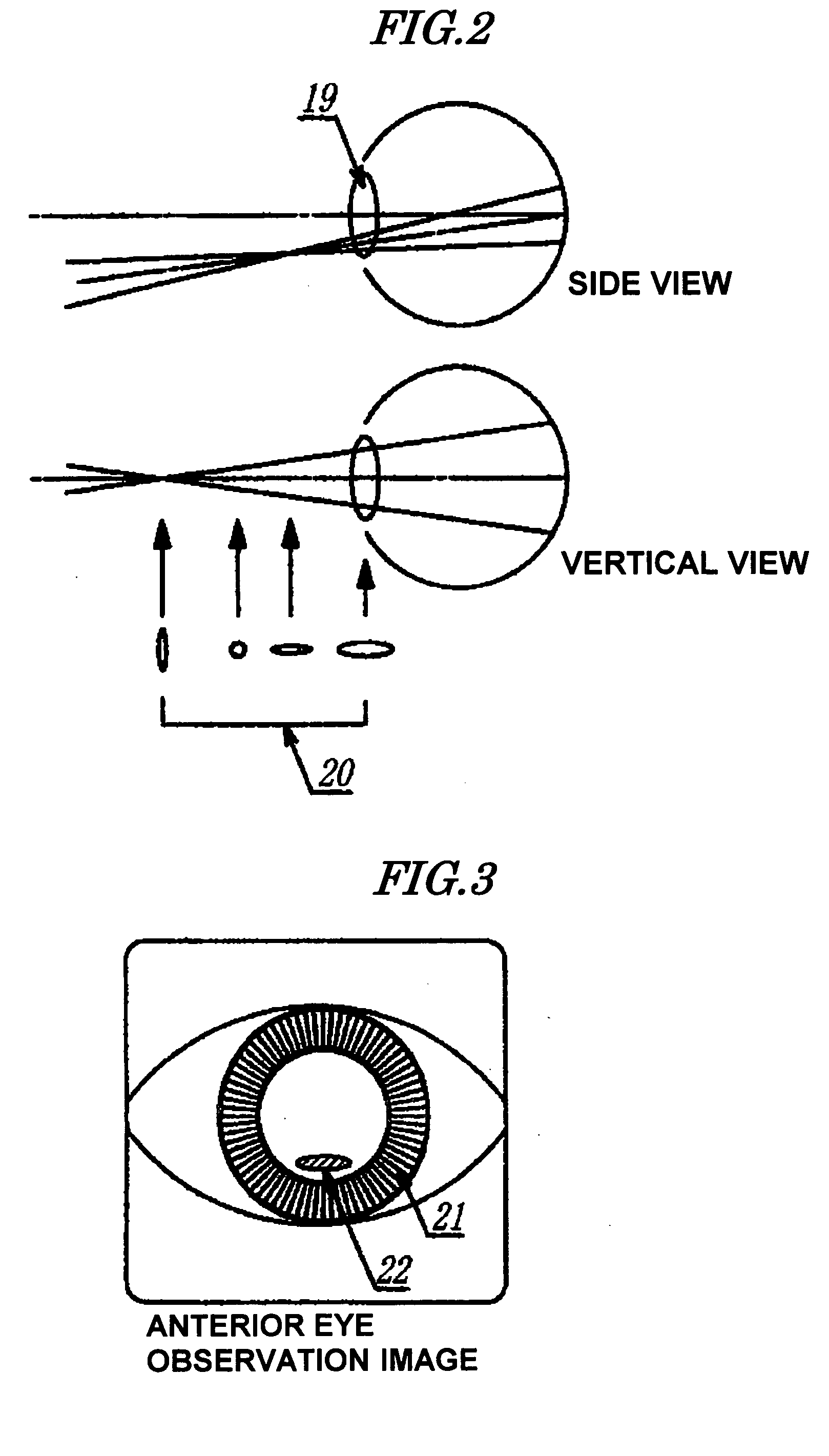
[0041] In the present invention, since the spot shape is rectangular when it passes through the pupil, it is possible to expand the spot along the edge of the pupil. It is therefore possible to irradiate as wide an area of the ocular fundus as possible while making the beam pass through just inside the pupil. Specifically, the laser beam preferably has a rectangular spot shape and is passed through a lower part and / or an upper par...


PUM


Abstract

With regard to a conventionally known ocular fundus blood flow imaging device, that is, a device in which the ocular fundus is irradiated with an expanded laser beam, light reflected from the ocular fundus is imaged on a 2-dimensional image sensor as a laser speckle, and a change over time of the laser speckle generated on the image plane is measured for each pixel to thus display an image as a blood flow map, a wide viewing angle ocular fundus blood flow imaging device in which the measurement field of view is enlarged includes a projection system that turns a laser beam into a rectangular spot on the ocular fundus, and an observation system that images the rectangular spot on an image sensor placed on the corresponding image plane. It is a clinically excellent and user-friendly wide viewing angle ocular fundus blood flow imaging device that is obtained by improving the conventional device in various aspects by incorporating an observation optical system for carrying out positioning of the laser spot, a mechanism for monitoring the movement of an ocular fundus blood vessel image, etc.

Description

TECHNICAL FIELD [0001] The present invention relates to an ocular fundus blood flow imaging device for measuring a blood flow state of the ocular fundus of a subject's eye. More particularly, the present invention relates to a wide viewing angle ocular fundus blood flow imaging device that is an improvement over a conventional device and is clinically superior. BACKGROUND ART [0002] When body tissue such as the ocular fundus is irradiated with a laser, the laser is scattered by particles forming the body tissue, and an intensity distribution of reflected scattered light forms a dynamic laser speckle (random spot pattern) due to moving scattering particles such as blood cells. It is known that by detecting this pattern with an image sensor at an imaging plane, quantifying the change over time of the pattern for each pixel, and displaying it as a map, the blood flow distribution of blood capillaries in the vicinity of the body surface can be imaged. [0003] There is a conventionally kn...

Claims


Application Information

Patent Timeline
Patent Type & Authority Applications(United States)
IPC IPC(8): A61B3/12
CPCA61B3/1233A61B3/0091
Inventor FUJII, HITOSHIKONISHI, NAOKI
Owner NAT UNIV CORP KYUSHU INST OF TECH (JP)
Why Eureka
Try Eureka