Gas laser apparatus for determining composition ratio of laser gas

a laser apparatus and composition ratio technology, applied in the direction of electrical apparatus, laser details, wave amplification devices, etc., can solve the problems reducing the laser output, and requiring a long time to restore the reduction of laser output, so as to reduce the laser output and reduce the laser output. , the effect of increasing the consumption of laser gas

Active Publication Date: 2016-08-04
FANUC LTD
View PDF2 Cites 2 Cited by
  • Summary
  • Abstract
  • Description
  • Claims
  • Application Information

AI Technical Summary

Benefits of technology

[0012]However, in Japanese Laid-open Patent Publication No. H4-80979, the predetermined amount of the laser gas is released outside without confirming the state of the laser gas. Due to this, even when no pin hole or the like is formed in the laser gas piping system, the laser gas will be released, which consequently increases the consumption of the laser gas. Additionally, when laser output is reduced due to helium gas leakage from the laser gas piping system or the carbon dioxide gas laser oscillator, it requires a long time to restore the reduction of the laser output.

Problems solved by technology

Due to this, even when no pin hole or the like is formed in the laser gas piping system, the laser gas will be released, which consequently increases the consumption of the laser gas.
Additionally, when laser output is reduced due to helium gas leakage from the laser gas piping system or the carbon dioxide gas laser oscillator, it requires a long time to restore the reduction of the laser output.
However, due to the changed composition ratio of the laser gas, originally desired oscillation efficiency cannot be obtained.
In such cases, since the carbon dioxide gas laser oscillator is started after performing an aging operation for long hours, it requires a long time to start.

Method used


Image

  • Gas laser apparatus for determining composition ratio of laser gas
  • Gas laser apparatus for determining composition ratio of laser gas
  • Gas laser apparatus for determining composition ratio of laser gas

Examples


Embodiment Construction

[0031]Hereinafter, exemplary embodiments of the present invention will be described with reference to the accompanying drawings. In the following drawings, the same members are denoted by the same reference signs. For easier understanding, scales of the drawings are changed as appropriate.

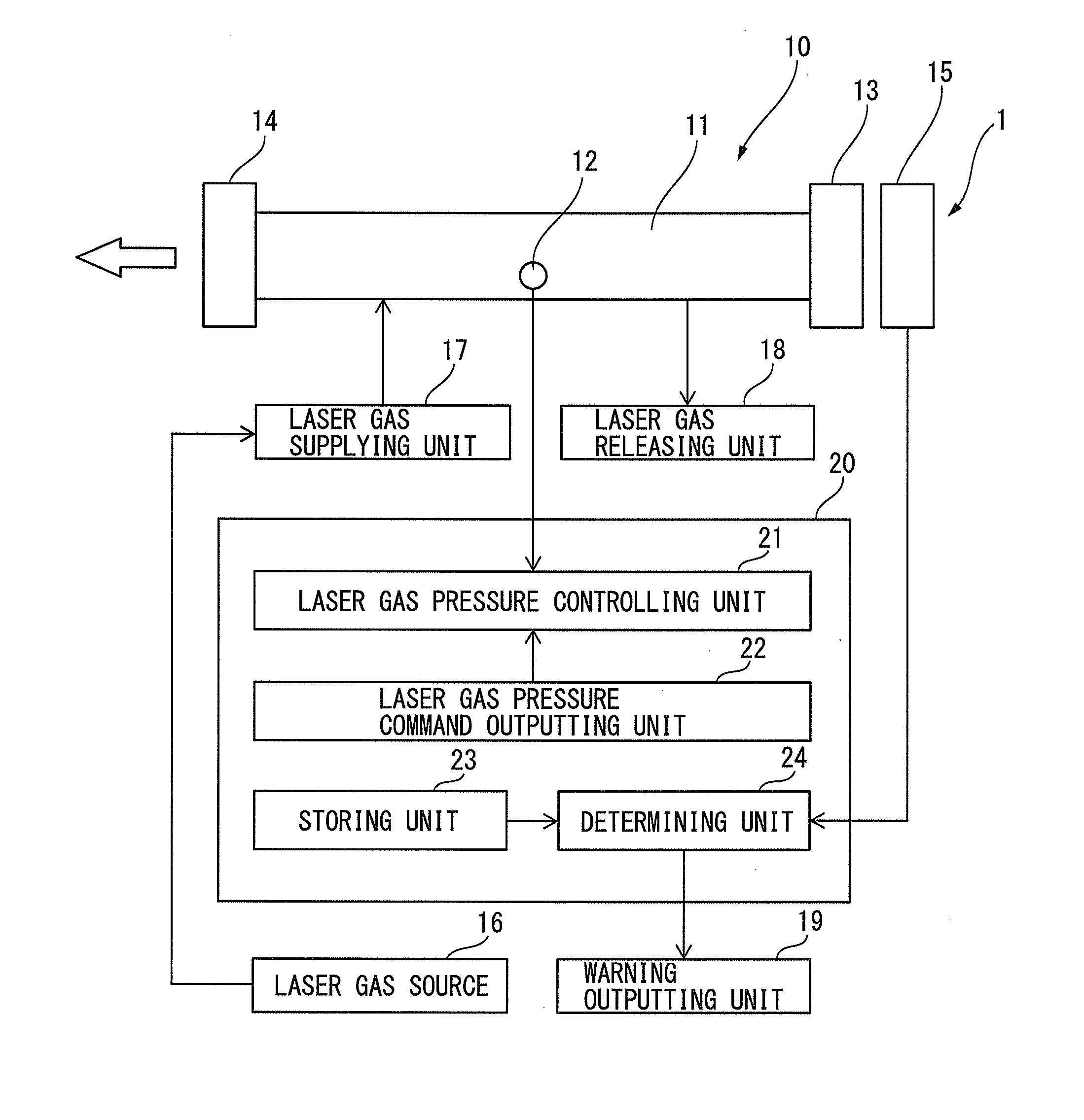
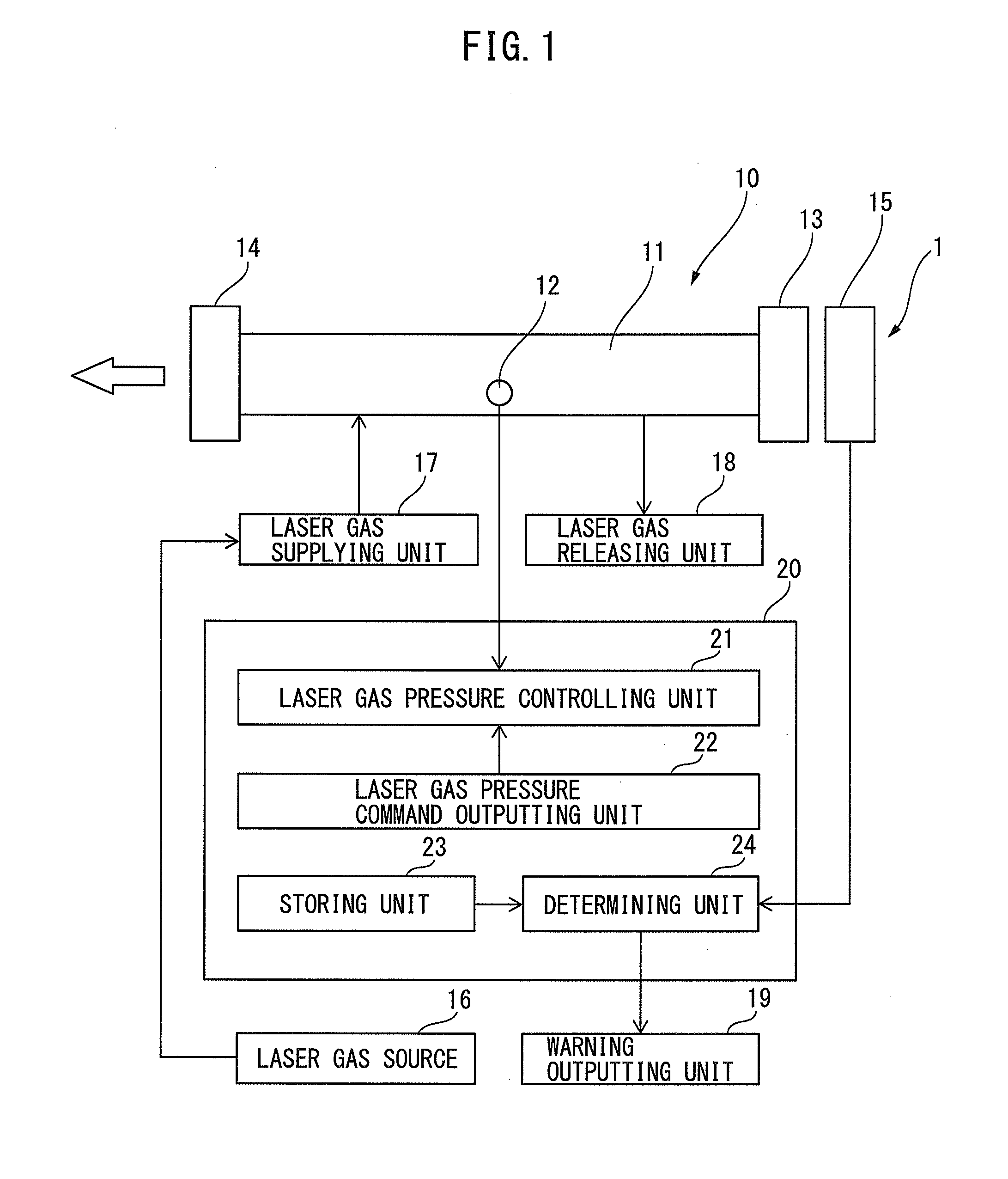
[0032]FIG. 1 is a schematic diagram of a carbon dioxide gas laser apparatus according to an embodiment of the present invention. A gas laser apparatus 1 denoted in FIG. 1 mainly includes a carbon dioxide gas laser oscillator 10 and a controlling unit 20 controlling the carbon dioxide gas laser oscillator 10. In addition, the carbon dioxide gas laser oscillator 10 is assumed to be connected to be a laser processing machine, although it is not depicted in FIG. 1.

[0033]As depicted in FIG. 1, the carbon dioxide gas laser oscillator 10 includes a gas container 11 containing a laser gas as a laser oscillating medium, for example, a discharge tube. A pressure acquiring unit 12 acquiring a pressure value o...


PUM


Abstract

A gas laser apparatus includes an actual laser output acquiring unit that acquires a first actual laser output at a predetermined laser output command after passage of a predetermined time from issuing of a first laser gas pressure command and acquires a second actual laser output at the predetermined laser output command after passage of the predetermined time from issuing of a second laser gas pressure command smaller than the first laser gas pressure command and a determining unit that determines whether the composition ratio of a laser gas in a gas container is normal or not by comparing the first actual laser output with a first reference output and comparing the second actual laser output with a second reference output smaller than the first reference output.

Description

BACKGROUND OF THE INVENTION[0001]1. Field of the Invention[0002]The present invention relates to a gas laser apparatus, in particular to a gas laser apparatus for determining the composition ratio of a laser gas.[0003]2. Description of the Related Art[0004]In carbon dioxide gas laser oscillators, a laser gas circulating at high speed in a gas container is electrically discharged by a power supply for electrical discharge excitation, thereby generating laser light. A sheet metal cutting laser processing machine can cut a metal material, a resin material, or the like using laser light output from a carbon dioxide gas laser oscillator. The laser gas includes carbon dioxide gas, nitrogen gas, and helium gas as main components. The laser gas, which was produced by a gas manufacturer, has a previously designated composition ratio of carbon dioxide gas, nitrogen gas, and helium gas. Such a laser gas is supplied to the carbon gas laser oscillator through a laser gas piping system.[0005]Howe...

Claims


Application Information

Patent Timeline
Patent Type & Authority Applications(United States)
IPC IPC(8): H01S3/097H01S3/00
CPCH01S3/0014H01S3/09705H01S3/036H01S3/134H01S3/2232
Inventor YUDA, KENICHITAKAZANE, TETSUHISA
Owner FANUC LTD
Why Eureka
Try Eureka