
Laser welding apparatus and laser processing device

a laser processing device and laser welding technology, applied in the direction of soldering devices, manufacturing tools, auxillary welding devices, etc., can solve the problems of excessive burr formation, crack formation in the welded, and insufficient pressing of the resin members against each other

Active Publication Date: 2022-03-17
PANASONIC INTELLECTUAL PROPERTY MANAGEMENT CO LTD +1
View PDF4 Cites 1 Cited by
  • Summary
  • Abstract
  • Description
  • Claims
  • Application Information

AI Technical Summary

Benefits of technology

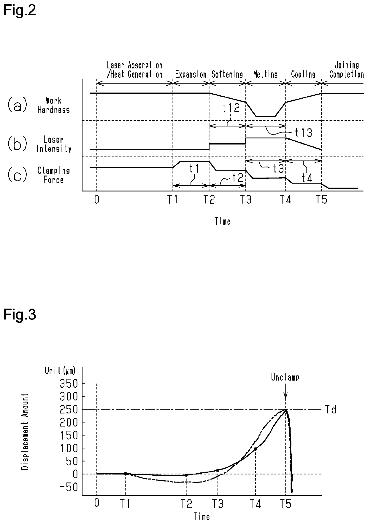
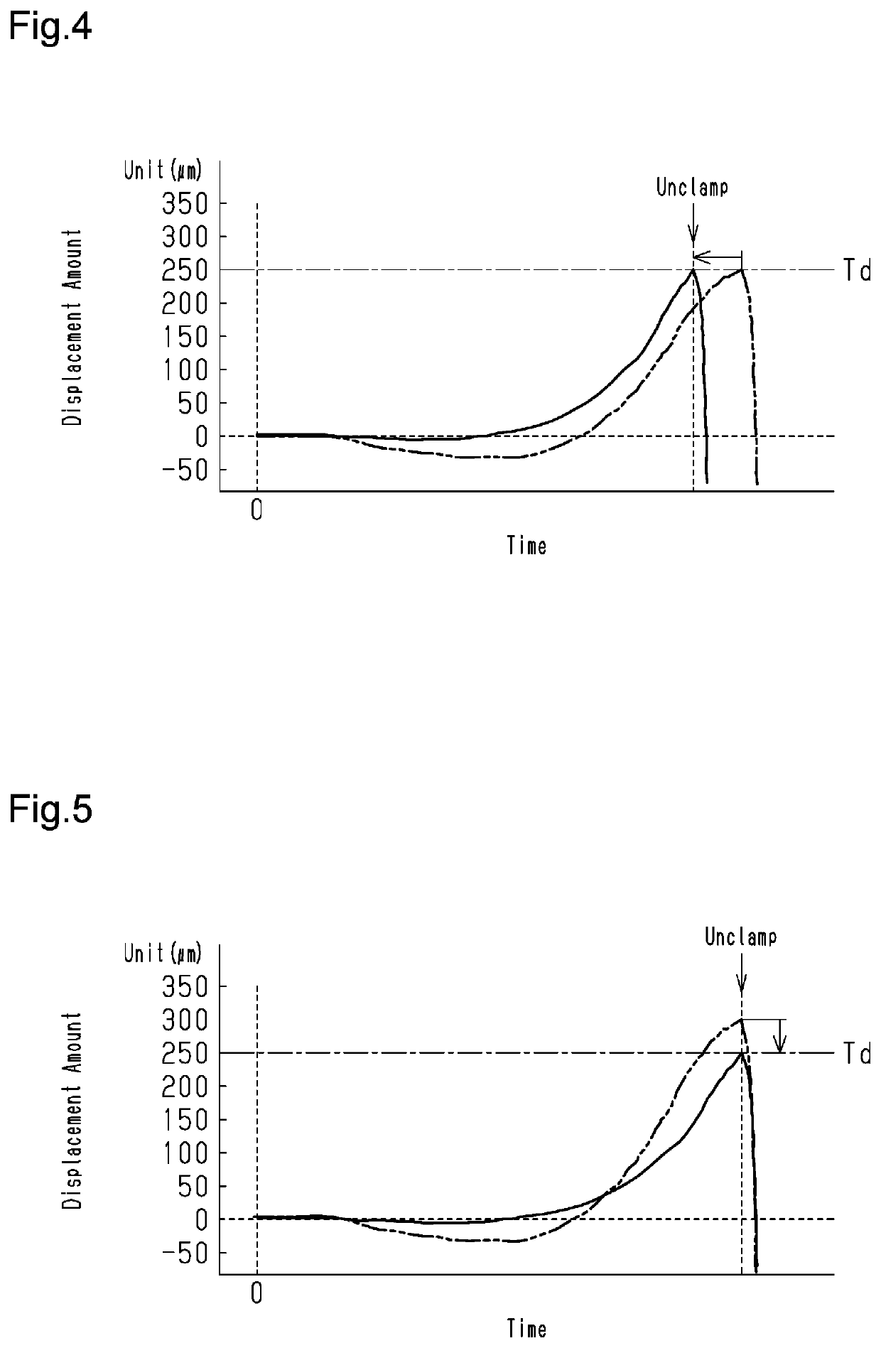
The patent describes a configuration for laser welding two resin members where a clamping force is applied to prevent burrs and cracks formation. The clamping force is adjusted based on the displacement of the resin members during laser welding, which prevents incomplete melting and joining of the resin members. Additionally, the laser output is gradually decreased to cool the resin members and reduce residual stress, further limiting the formation of cracks.

Problems solved by technology

The application of excessive clamping force to the two resin members during laser welding may result in, for example, the formation of excessive burrs or the formation of cracks in the welded resin members caused by residual stress.
The application of clamping force that is too small to the two resin members during laser welding may result in insufficient pressing of the resin members against each other.
When the resin members are pressed against each other insufficiently, fine gaps will form between the contact surfaces of the two resin members, which are arranged one upon the other.
Further, the laser beam-transmissive resin member may not be melted adequately due to the insufficient transfer of heat from the laser beam-absorbing resin member.
However, in Japanese Laid-Open Patent Publication Nos. 2006-44122 and 2008-254404, the clamping force applied to the two resin members is not adjusted during laser welding.
Thus, depending on the adjustment of the clamping force applied to the two resin members prior to laser welding, the formation of excessive burrs or the formation of cracks may occur in the welded resin members.
As described in Japanese Laid-Open Patent Publication No. 2007-111927, when the temperature at the contact surfaces of the two resin members is detected and the clamping force applied to the two resin members is adjusted in accordance with the detected temperature during laser welding, adjustment of the clamping force will be difficult if the detected temperature change is subtle.
Thus, the clamping force applied to the two resin members may not appropriately be in accordance with the state of the resin members during laser welding.
As a result, the formation of burrs and cracks is limited in the first resin member and the second resin member.
As a result, the formation of cracks is further limited in the first resin member and the second resin member.
As a result, the formation of burrs and cracks is further limited in the first resin member and the second resin member.
As a result, the formation of cracks is further limited in the first resin member and the second resin member.

Method used


Image

  • Laser welding apparatus and laser processing device
  • Laser welding apparatus and laser processing device
  • Laser welding apparatus and laser processing device

Examples


Embodiment Construction

[0043]This description provides a comprehensive understanding of the methods, apparatuses, and / or systems described. Modifications and equivalents of the methods, apparatuses, and / or systems described are apparent to one of ordinary skill in the art. Sequences of operations are exemplary, and may be changed as apparent to one of ordinary skill in the art, with the exception of operations necessarily occurring in a certain order. Descriptions of functions and constructions that are well known to one of ordinary skill in the art may be omitted.

[0044]Exemplary embodiments may have different forms, and are not limited to the examples described. However, the examples described are thorough and complete, and convey the full scope of the disclosure to one of ordinary skill in the art.

[0045]An embodiment of a laser welding apparatus will now be described with reference to the drawings.

[0046]The drawings may not be to scale, and the relative size, proportions, and depiction of elements in th...


PUM

PropertyMeasurementUnit
clamping forceaaaaaaaaaa
displacementaaaaaaaaaa
thermal expansionaaaaaaaaaa

Abstract

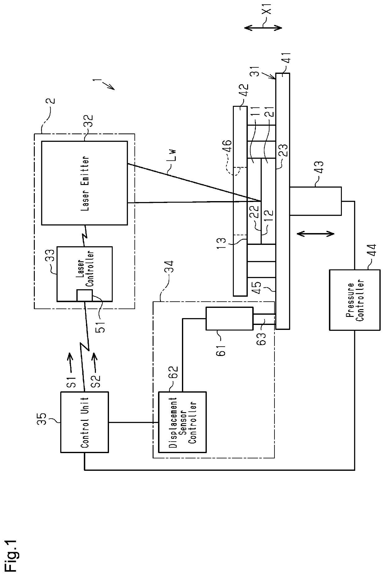
A first resin member including a first contact surface and formed of laser beam-transmissive resin and a second resin member including a second contact surface, which contacts the first contact surface, and formed of laser beam-absorbing resin are arranged one upon the other. A laser welding apparatus includes a clamping unit abutting the second resin member and applying clamping force to the second resin member, a laser emitter emitting laser beam, a laser controller controlling output of the laser beam, a displacement sensor measuring displacement of the second contact surface in stacking direction of the resin members, and a control unit controlling the clamping unit to adjust the clamping force corresponding to displacement amount of the second contact surface continuously or intermittently obtained from the displacement sensor.

Description

CROSS-REFERENCE TO RELATED APPLICATION[0001]The present application claims priority under 35 U.S.C. § 119(a) to Japanese Patent Application No. 2020-155523, filed on Sep. 16, 2020, which is incorporated herein by reference in its entirety.1. FIELD[0002]The following description relates to a laser welding apparatus and a laser processing device.2. DESCRIPTION OF RELATED ART[0003]A typical laser welding apparatus joins two resin members arranged one upon the other by laser welding. There are various types of laser welding apparatuses that perform laser welding while applying pressure with a jig, such as a clamp, to press the surfaces of the two resin members against each other so that the resin members can be welded sufficiently.[0004]Japanese Laid-Open Patent Publication No. 2006-44122 describes an example of a laser welding apparatus that clamps two resin members by a clamp claw and detects the reactive force acting on the clamp claw. Then, the clamping force applied by the clamp cl...

Claims


Application Information

Patent Timeline
Patent Type & Authority Applications(United States)
IPC IPC(8): B23K37/04B23K26/03B23K26/06B29C65/14B29C65/00
CPCB23K37/0435B23K26/03B29C66/81B29C65/1435B29C66/95B23K26/0626B29C66/1122B29C66/41B29C66/8322B29C66/9231B29C66/92441B29C66/961B29C66/8242B29C66/8246B29C66/73921B29C65/1638B29C65/1654B29C66/934B29C66/92921B29C66/92445B29C66/91951B29C66/91645B29C66/73151B29C66/9592B29C66/81267B29C66/8122B29K2909/08B29K2905/00
Inventor INOUE, KOSUKEKAEDE, YUJIKUMAMOTO, SHUKUNIEDA, HIDEAKI
Owner PANASONIC INTELLECTUAL PROPERTY MANAGEMENT CO LTD
Learn More