
Method and Apparatus for Video Mixing

Inactive Publication Date: 2007-12-13
DILITHIUM HOLDINGS INC
View PDF8 Cites 39 Cited by
  • Summary
  • Abstract
  • Description
  • Claims
  • Application Information

AI Technical Summary

Benefits of technology

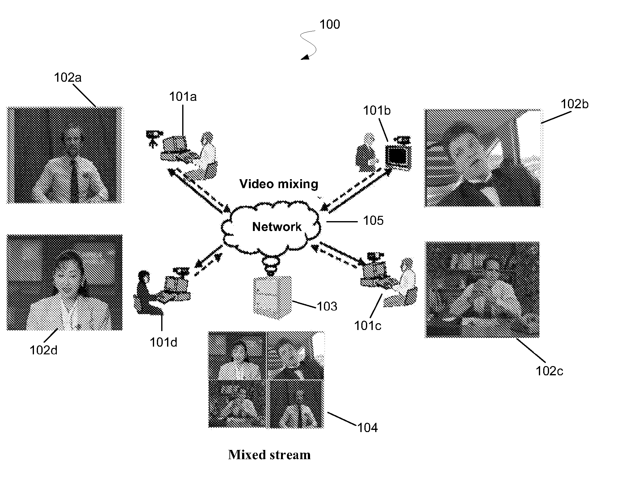
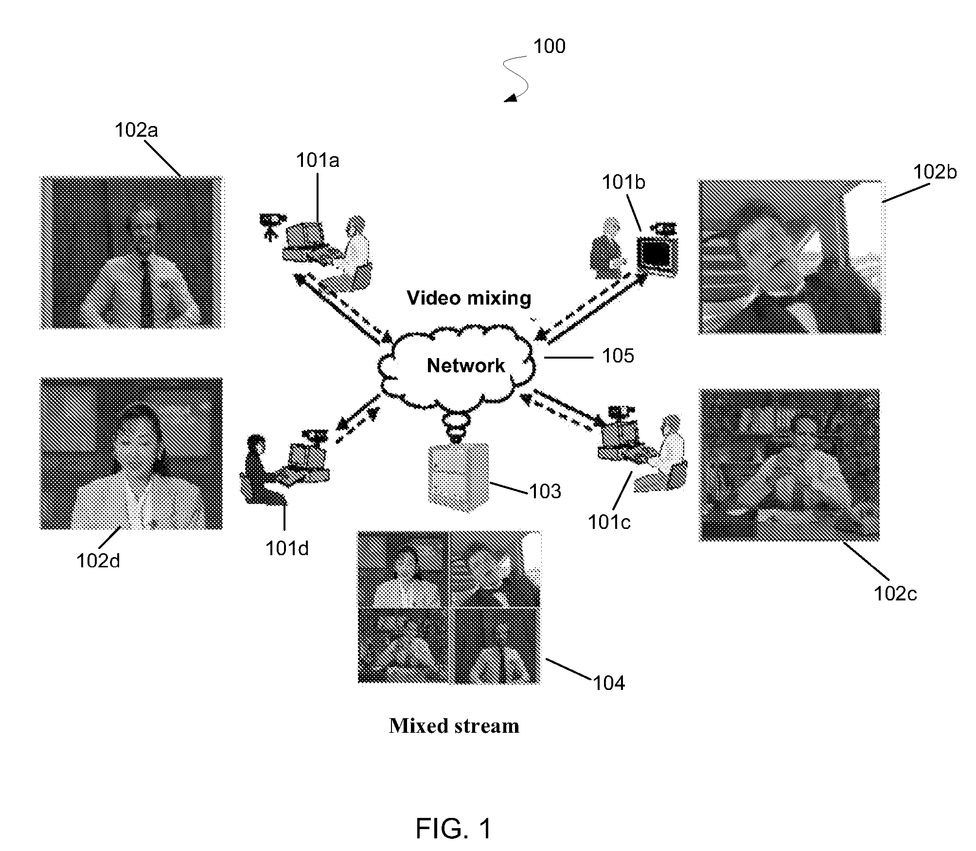
[0011] The present invention relates to methods and systems for mixing a plurality of compressed input video streams into one or more compressed video output streams for multipoint video conferencing applications. Embodiments of the present invention maintain flexibility with respect to input / output compression formats and resolution while providing low computation costs.
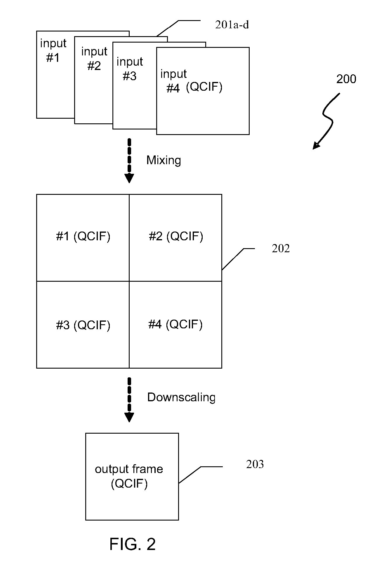
[0012] According to an embodiment of the present invention, methods and apparatus for video mixing of video bitstreams from multiple mobile clients in a conferencing gateway are provided. The apparatus is able to receive multiple video streams encoded with a same frame size (i.e., QCIF, CIF, and the like) but by different video standards, such as H.263, H.264, MPEG4, or the like. The apparatus is able to output a mixed video stream back to each client with a frame size and video format the same as the input stream. The input video streams are unpacked to a parameter domain where mixing and downscaling are performed and the mixed streams are packed according to the video format of each client. Thus, embodiments of the present invention provide for the combination of three or more modules, including a mixed macro-block (MB) coding mode decision module, a selective coefficient mixing and downscaling module, and an adaptive motion vector (MV) re-sampling and refinement module. Embodiments of the present invention provide a substantial savings in computational costs, a marginal savings on the bit-rate, and a mixed video bitstream with little to no video quality loss.
[0015] Embodiments of the present invention provide numerous benefits in comparison with convention techniques. For example, an embodiment performs video mixing while avoiding full decoding and full encoding by mixing in a video parameter domain. Another embodiment reuses pre-encoded video data from input video streams and selectively activates mixing and downscaling processes. Compared with conventional full decoding, full mixing in picture spatial domain, full scaling in spatial domain and full decoding approaches, embodiments of the present invention reduce computation costs, particular costs associated with motion estimation processes used during full encoding.
[0016] Additional benefits provided herein include achieving better video quality of the output mixed video stream by predicting the motion data for the mixed output macroblocks in the compressed video parameter domain. Further benefits include reduction of latency by producing a mixed output in a macro-block based manner before an entire associated input video frame is received. Thus, embodiments of the present invention reduce both algorithm delay and processing delay.
[0017] Yet further benefits of the present invention include reduced memory usage by performing video mixing in a macro-block based manner, thus utilizing adjoining macroblocks information, which constitutes only a small portion of a frame. Some embodiments utilize advanced rate control mechanisms using pre-encoded compression parameter and motion information from input video streams, thereby reducing the bandwidth fluctuations or the bandwidth of the mixed video bitstream.

Problems solved by technology

Conventional multi-point video communication solution requires heavy and expensive computation resources.
Such conventional methods are computationally expensive due to the full motion estimation process used to encode the mixed output video stream.
Since the processes of frame-based frame downscaling and full re-encoding are very computationally intensive, particularly with full-scale motion estimation (ME) and an exhaustive MB mode selection (i.e., intra and inter) in H.263 encoding, such video mixing approaches usually represent a solution with very low computational efficiency.

Method used


Image

  • Method and Apparatus for Video Mixing
  • Method and Apparatus for Video Mixing
  • Method and Apparatus for Video Mixing

Examples


Embodiment Construction

[0037] A method and an apparatus of the present invention are discussed in detail below. In the following description, for purposes of explanation, numerous specific details are set forth in order to provide a thorough understanding of the present invention. A person skilled in the art will recognize that other steps and applications than those listed here as examples are possible without departing from the spirit of the present invention.

[0038] An exemplary embodiment of the present invention processes multiple video stream inputs and manages video conferencing for up to five attendees. The attendees use multimedia (audio, video and data) terminals, such as PDAs or smart phones such as 3G-324M video telephones, to send and receive compressed video streams. It is likely that all the input streams for conference attendees are in the same video resolution or frame size (i.e. QCIF or CIF). However they may be encoded by different video standards, such as H.263, H.264 / AVC or MPEG4. The...


PUM


Abstract

An apparatus for use in video mixing of multiple video sources compressed in one or more video codecs includes a bitstream unpacker configured to receive and unpack each of the multiple video sources to provide intermediate video parameters including transform-domain coefficients, frame header information, macroblock header information, and motion vector data. The apparatus also includes an intermediate coefficient buffer coupled to the bitstream unpacker and a decision module coupled to the bitstream unpacker. The apparatus further includes a transform-domain coefficient downscaling module coupled to the intermediate coefficient buffer, a motion vector refinement module coupled to the bitstream unpacker, and a bitstream packer coupled to the decision module, the transform-domain coefficient downscaling module, and the motion vector refinement module. The bitstream packer is configured to output multiple video output streams in an output frame and the multiple output streams are compressed using the one or more video codecs.

Description

CROSS-REFERENCES TO RELATED APPLICATIONS [0001] The present application claims priority to U.S. Provisional Patent Application No. 60 / 793,746, filed on Apr. 21, 2006, which is commonly owned and hereby incorporated by reference in its entirety for all purposes.FIELD OF THE INVENTION [0002] The present invention relates generally to digital video signal processing. More particularly, the invention provides a method and an apparatus for the mixing of compressed video streams from multiple devices into a mixed stream sent back to each device in the same video size and format as the input. Merely by way of example, the invention has been applied to the mixing of compressed video streams from multiple conferees in a conferencing gateway, but it would be recognized that the invention may also include other applications. BACKGROUND OF THE INVENTION [0003] With the great success of several international video standards, such as H.261, H.263, MPEG4, and H.264 / AVC, video communication and vid...

Claims


Application Information

Patent Timeline
IPC IPC(8): H04N7/14
CPCH04N7/152H04N19/105H04N19/103H04N19/59H04N19/124H04N19/533H04N19/40H04N19/109
Inventor MA, ZHONGHUAWANG, JIANWEIJABRI, MARWAN A.
Owner DILITHIUM HOLDINGS INC
Learn More