Eureka AIR delivers breakthrough ideas for toughest innovation challenges, trusted by R&D personnel around the world.

Vehicle and control method of vehicle

a technology of vehicle and control method, which is applied in the direction of braking system, braking components, transportation and packaging, etc., can solve the problems of inability to immediately satisfy the braking force demand in response to the driver's braking operation, undesirably long braking time or braking distance,

Inactive Publication Date: 2007-11-22
TOYOTA JIDOSHA KK
View PDF4 Cites 40 Cited by
  • Summary
  • Abstract
  • Description
  • Claims
  • Application Information

AI Technical Summary

Benefits of technology

[0006]In a vehicle equipped with a fluid pressure braking structure having multiple braking systems that respectively include a pressurization unit for pressurization of an operation fluid and are related to respective specified wheels among multiple wheels, there is a need of ensuring satisfaction of a braking force demand required by the driver even in the event of some abnormality in pressurization of the operation fluid in any of the multiple braking systems. There is also a need of enhancing the safety during braking control of the vehicle.
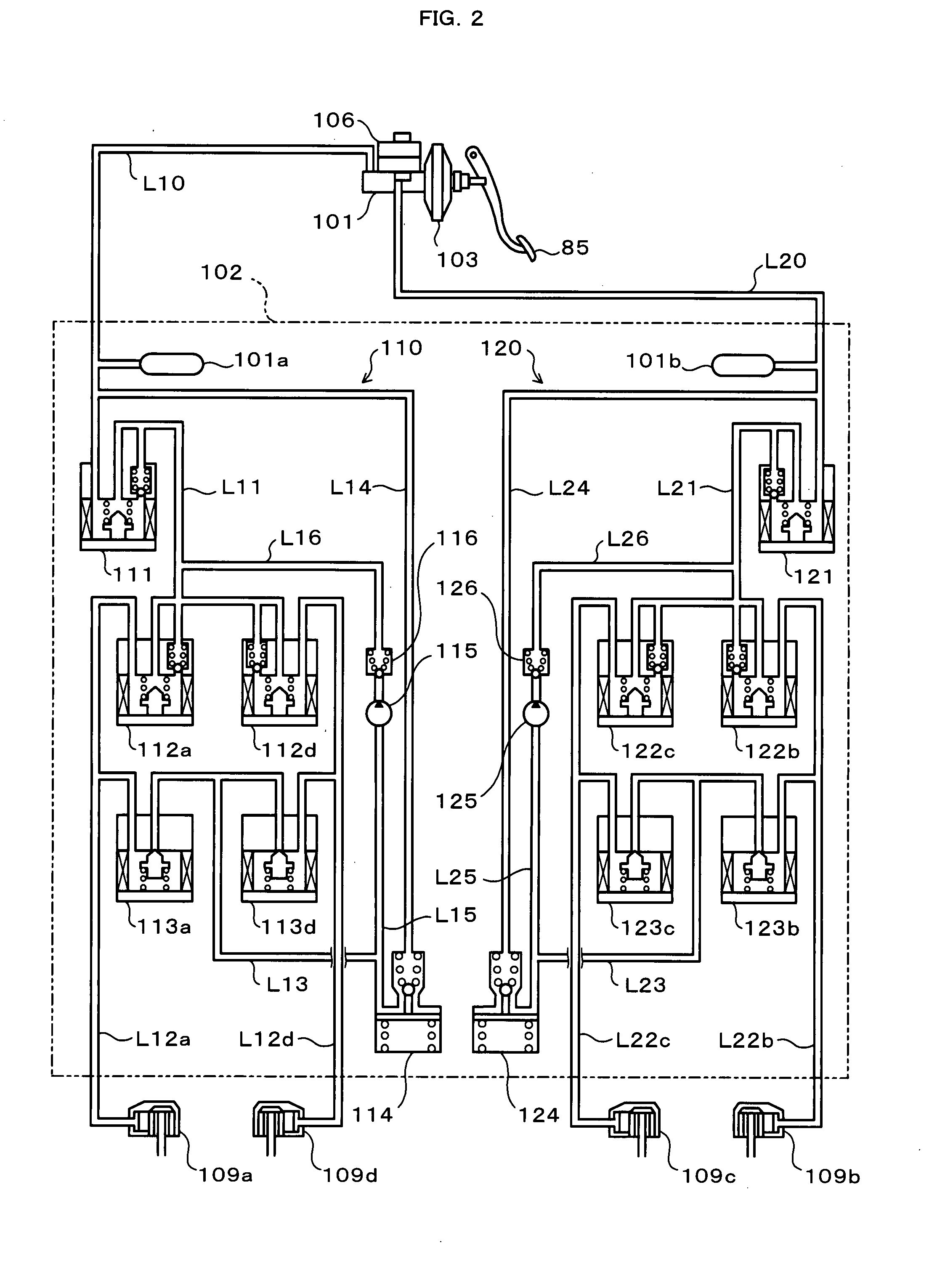
[0009]The vehicle of the invention has the fluid pressure braking structure including the multiple braking systems, which respectively have the pressurization unit for pressurization of the operation fluid and are related to the respective specified wheels among the multiple wheels. The braking force is output from the multiple braking systems of the fluid pressure braking structure by utilizing the operational pressure of the operation fluid produced by the driver's braking operation and the pressure increase induced by pressurization of the operation fluid by the respective pressurization units. In the case of no detection of any abnormity in the multiple braking systems that causes failed pressurization of the operation fluid by the pressurization unit, the fluid pressure braking structure is controlled to enable pressurization of the operation fluid by the respective pressurization units of the multiple braking systems and to ensure satisfaction of the braking force demand, which is required by the driver's braking operation, based on the operational pressure and the pressure increase by the respective pressurization units of the multiple braking system. In the case of detection of an abnormality in any of the multiple braking systems, on the other hand, the fluid pressure braking structure is controlled to enable pressurization of the operation fluid by the pressurization unit of only the normal braking system among the multiple braking systems and to ensure satisfaction of the braking force demand based on the operational pressure and the pressure increase by the pressurization unit of only the normal braking system. Even in the event of a failure or abnormality in any of the multiple braking systems to cause failed pressurization of the operation fluid, the vehicle of the invention ensures satisfaction of the braking force demand required by the driver by utilizing the operational pressure and the pressure increase by the pressurization unit of each normal braking system and to enhance the safety during braking control.
[0011]The vehicle of the invention may further include: a motor that is driven to output at least a regenerative braking force; an accumulator unit that inputs and outputs electric power from and to the motor; a braking force demand setting module that sets a braking force demand required by the driver, in response to the driver's braking operation; and a pressurization command value setting module that sets a pressurization command value for the pressurization unit of each normal braking system, based on the set braking force demand, the regenerative braking force output from the motor, an operational braking force based on the operational pressure, and a result of the abnormality detection by the abnormality detection module, wherein the braking control module may control the motor and the fluid pressure braking structure to actuate the pressurization unit of each normal braking system with the set pressurization command value and to ensure satisfaction of the set braking force demand. In the vehicle equipped with the motor for outputting the regenerative braking force, the pressure increase-based braking force by each pressurization unit may be used to compensate for an insufficiency of the operational pressure-based operational braking force and the regenerative braking force generated by the motor. Even in the event of failed pressurization of the operation fluid by any failure or abnormality in any of the multiple braking systems, this aspect of the invention ensures satisfaction of the braking force demand.
[0012]The vehicle of the invention may further include: an operational pressure measurement unit that measures the operational pressure of the operation fluid produced by the driver's braking operation; and a regenerative braking force setting module that sets a regenerative braking force generated by regeneration of the motor, in response to the driver's braking operation, wherein the pressurization command value setting module may set the pressurization command value for the pressurization unit of each normal braking system, based on a result of subtraction of the set regenerative braking force and an operational braking force based on the measured operational pressure from the set braking force demand, as well as based on the result of the abnormality detection by the abnormality detection module. This aspect of the invention enables adequate setting of the pressurization command value for each pressurization unit.
[0016]Even in the event of a failure or abnormality in any of the multiple braking systems to cause failed pressurization of the operation fluid, the control method of the vehicle of the invention ensures satisfaction of the braking force demand required by the driver by utilizing the operational pressure and the pressure increase by the pressurization unit of each normal braking system.

Problems solved by technology

When the pressure regulation of the brake oil is disabled by a failure or abnormality occurring in any of the multiple hydraulic systems in the brake actuator, it is impossible to immediately satisfy a braking force demand in response to the driver's braking operation.
This may lead to the undesirably long braking time or braking distance.

Method used


Image

  • Vehicle and control method of vehicle
  • Vehicle and control method of vehicle
  • Vehicle and control method of vehicle

Examples


Embodiment Construction

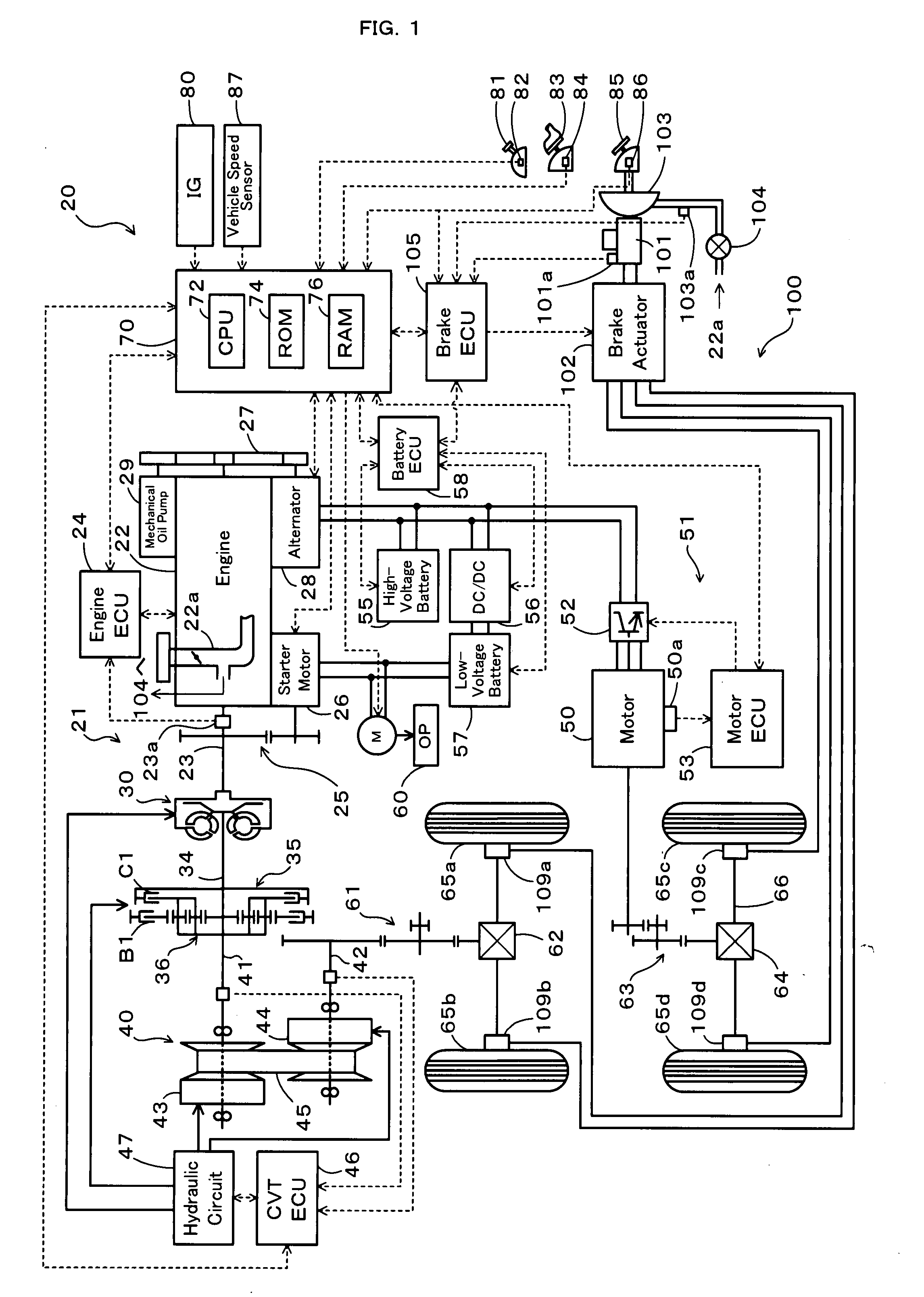
[0029]One mode of carrying out the invention is described below as a preferred embodiment. FIG. 1 schematically illustrates the configuration of a hybrid vehicle 20 in one embodiment of the invention. The hybrid vehicle 20 of the embodiment has a front wheel driving system 21 for transmission of output power of an engine 22 to front wheels 65a and 65b via a torque converter 30, a forward-backward drive switchover mechanism 35, a belt-driven continuously variable transmission (hereafter referred to as ‘CVT’) 40, a gear mechanism 61, and a differential gear 62, a rear wheel driving system 51 for transmission of output power of a motor 50 to rear wheels 65c and 65d via a gear mechanism 63, a differential gear 64, and a rear axle 66, an electronically controlled hydraulic braking system (hereafter referred to as ‘HBS’) 100 for application of braking force to the front wheels 65a and 65b and to the rear wheels 65c and 65d, and a hybrid electronic control unit (hereafter referred to as ‘h...


PUM


Abstract

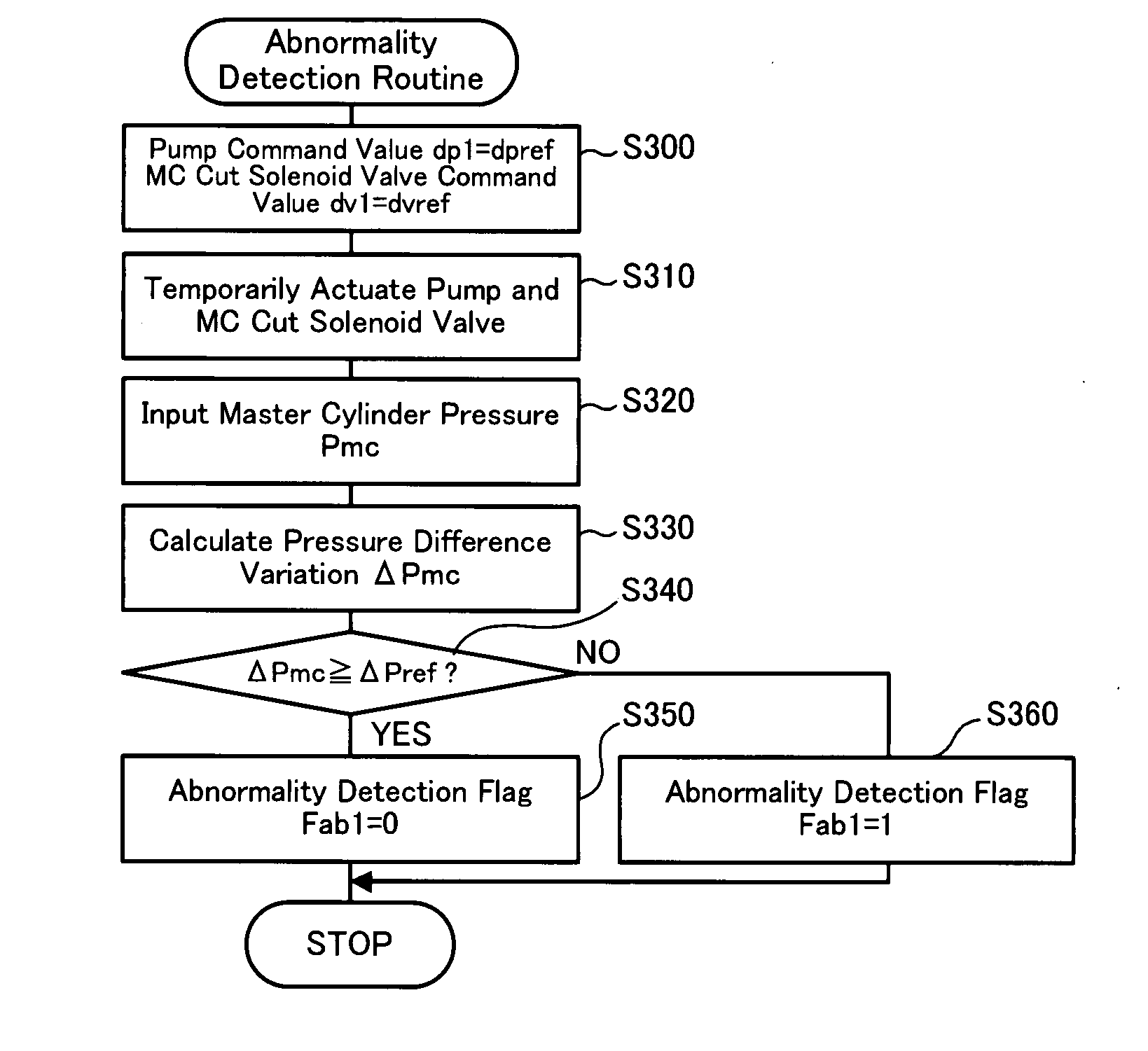
In the case of detection of any abnormality in either of a first braking system and a second braking system of a brake actuator, which causes failed pressurization of brake oil, an electronically-controlled hydraulic braking system is controlled to enable pressurization of the brake oil with a pump included in only a normal braking system, that is, only with a pump of a normal first braking system or only with a pump of a normal second braking system. Such pressurization ensures satisfaction of a braking force demand BF* required by the driver by utilizing an operational pressure or master cylinder pressure Pmc and a pressure increase induced by pressurization of the brake oil by the pump in the normal braking system (step S220 or S230 and step S210).

Description

BACKGROUND OF THE INVENTION[0001]1. Field of the Invention[0002]The present invention relates to a vehicle and a control method of the vehicle. More specifically the invention pertains to a vehicle equipped with a fluid pressure braking system, as well as to a corresponding control method of such a vehicle.[0003]2. Description of the Related Art[0004]In one known structure of a braking system for a vehicle, a pressure regulator regulates the liquid pressure, which is generated by a liquid pressure generator including an accumulator and a power-driven pump, according to the driver's pressing force of a brake pedal and outputs the regulated liquid pressure. A master cylinder is actuated by a supply of the liquid pressure to an auxiliary liquid pressure chamber. Both the output liquid pressures of the master cylinder and the pressure regulator are supplied to wheel cylinders, so as to apply a braking force to the wheels of the vehicle (see, for example, Japanese Patent Laid-Open Gazett...

Claims


Application Information

Patent Timeline
Patent Type & Authority Applications(United States)
IPC IPC(8): B60T8/88
CPCB60K6/44Y02T10/6265B60K6/543B60T1/10B60T8/442B60T8/4872B60T8/94B60T17/18B60T2270/402B60T2270/604B60W10/08B60W10/184B60W20/00Y02T10/623B60K6/52Y02T10/62B60W20/50B60W10/188
Inventor SHIMADA, MICHIHITOKODAMA, SHINYAMAKI, KAZUYA
Owner TOYOTA JIDOSHA KK
Why Eureka
Eureka Blog
Learn More