
Method of and apparatus for sticking tape on reel hub and method of and apparatus for winding tape on tape reel in tape cartridge

a technology of tape winding and tape end portion, which is applied in the direction of thin material processing, data recording, instruments, etc., can solve the problems of radial winding irregularity, possible excess of stick liquid applied quantitatively, and failure of sticking of tape end portion to the reel hub, etc., and achieves high yield rate

Inactive Publication Date: 2007-11-15
FUJIFILM CORP
View PDF4 Cites 13 Cited by
  • Summary
  • Abstract
  • Description
  • Claims
  • Application Information

AI Technical Summary

Benefits of technology

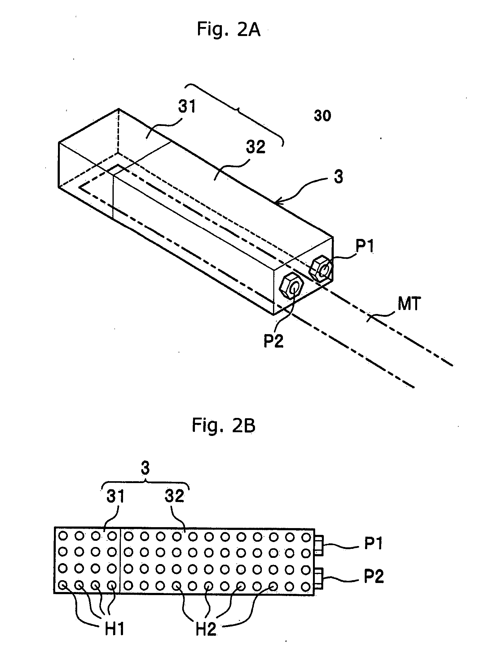
[0009] According to the tape end sticking apparatus, the liquid applying means having a sponge pad instilled with a sticking liquid is moved so as to bring the sponge pad into contact with an tape end portion of tape strip grasped by the tape carrier means, thereby applying an adequate spread of the sticking liquid to the reel hub and / or the tape end portion in a desired pattern. When the tape carrier means is moved to the reel hub of the tape reel in an empty cartridge case, the tape end portion is released from the tape carrier means and stuck on the reel hub with the sticking liquid. Since the spread pattern of sticking liquid has a width smaller at a rearmost end than a foremost end thereof an adequate spread of sticking liquid is applied in a desired pattern, sticking and winding of the tape strip are steadily performed. The liquid applying means has a sponge pad out of an empty cartridge case, the liquid applying means and the sponge pad can be designed freely without restraints on their sizes. It is preferred to use water or alcohol including methanol, ethanol, isopropanol (EPA), etc. as the sticking liquid.
[0010] It is preferred that the spread pattern has a foremost end of a width greater than a leading end of the tape strip in order to secure stable sticking of an tape end portion on a reel hub. Further, the spread pattern has a length smaller than a circumferential length of the reel hub in order to prevent convolutions of the tape end portion of magnetic tape strip MTa on the reel hub H after a second convolution being rubbed by one another through the sticking liquid and causing slips among.
[0014] According to the tape end sticking method, while an empty cartridge case is set in the cartridge setting chamber so as to permit the tape reel to rotate, a tape end portion of tape strip is grasped by the tape carrier means. Then, the liquid applying means having the sponge pad instilled with a sticking liquid is moved to the tape carrier means is moved toward the empty cartridge case and brings the sponge pad into contact with the tape end portion. In this way, an adequate spread of sticking liquid is applied to the tape end portion in a desired pattern. Subsequently, the tape carrier means is moved into the tape cartridge case though the egress / ingress opening to bring the tape end portion in close proximity to the reel hub and then releases the tape end portion therefrom so as thereby to stick it to the reel hub. In this way, the sticking liquid is applied to the tape end portion in a spread pattern having a width smaller at a rearmost end than a foremost end thereof an adequate spread of sticking liquid is applied in a desired pattern. In consequence, sticking of the tape end portion on the reel hub is steadily performed. The liquid applying means has a sponge pad out of an empty cartridge case, the liquid applying means and the sponge pad can be designed freely without restraints on their sizes. It is preferred to use water or alcohol including methanol, ethanol, isopropanol (IPA), etc. as the sticking liquid.
[0015] It is preferred that the spread pattern has a foremost end of a width greater than a leading end of the tape strip in order to secure stable sticking of an tape end portion on a reel hub. Further, the spread pattern has a length smaller than a circumferential length of the reel hub in order to prevent convolutions of the tape end portion of magnetic tape strip MTa on the reel hub H after a second convolution being rubbed by one another through the sticking liquid and causing slips among.
[0018] The method of and apparatus for sticking a tape end portion of tape strip on a reel hub of a tape reel installed in an empty cartridge realizes secured sticking of the tape end portion of tape strip on the reel hub. Further, the method of and apparatus for winding a tape strip on a reel hub of a tape reel installed in an empty cartridge realizes secured sticking of the tape end portion of tape strip on the tape reel, so as to prevent an occurrence of a radial winding irregularity in a roll of tape strip wound on the tape reel and, as a result, produce magnetic tape cartridges at a high yield rate.

Problems solved by technology

A problem encountered by the tape sticking device is that, because the sticking liquid is distributed uniformly in a tape width direction on the tape end portion, the sticking liquid is possibly applied in quantitatively excess.
Such an excessive sticking liquid application causes slippage between the tape end portion and the reel hub which accounts for offset sticking of the tape end portion relative to the reel hub or a failure in sticking the tape end portion relative to the reel hub at worst.
In other cases, a redundant sticking liquid runs off from between the tape end portion and the reel hub and is left as adhesion vestiges on flanges which are undesirable in appearance.
On the other hand, if applying a decreased quantity of sticking liquid to a central portion of the reel hub in order to prevent the sticking liquid from running off, sticking of the tape end portion to the reel hub possibly ends in failure, partly or entirely.
Particularly, if such a failure occurs, the tape end portion is apt to cause a turnup or a bend at its edge which leads to a radial winding irregularity in a roll of tape strip.

Method used


Image

  • Method of and apparatus for sticking tape on reel hub and method of and apparatus for winding tape on tape reel in tape cartridge
  • Method of and apparatus for sticking tape on reel hub and method of and apparatus for winding tape on tape reel in tape cartridge
  • Method of and apparatus for sticking tape on reel hub and method of and apparatus for winding tape on tape reel in tape cartridge

Examples


Embodiment Construction

[0027] The present invention is suitable for use on all types of tape cartridges and has particular application in the assembling of tape cartridges which are compliant with Linear Tape Open (LTO) standard. However, it should be appreciated that the invention has broader application and is not limited to this particular use.

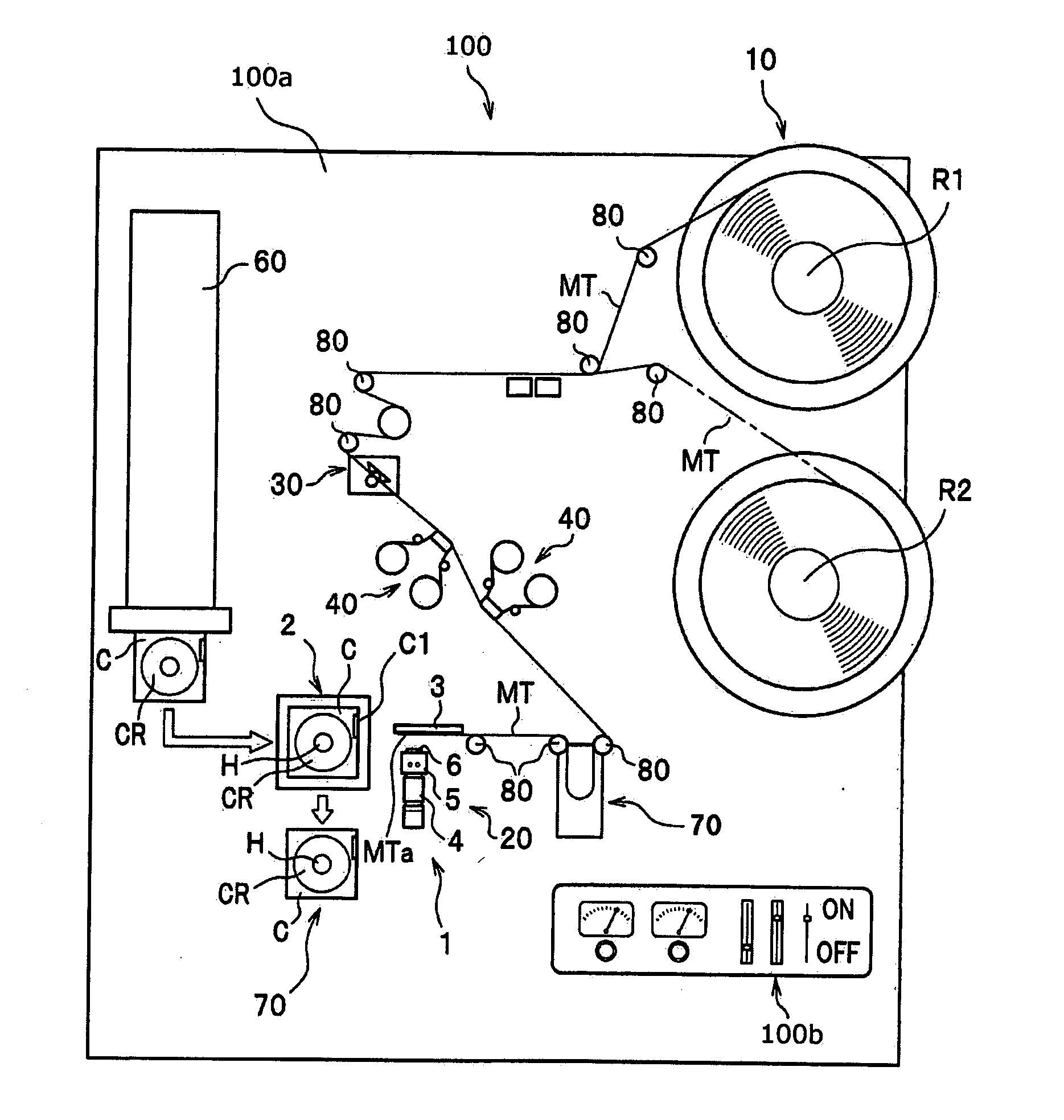
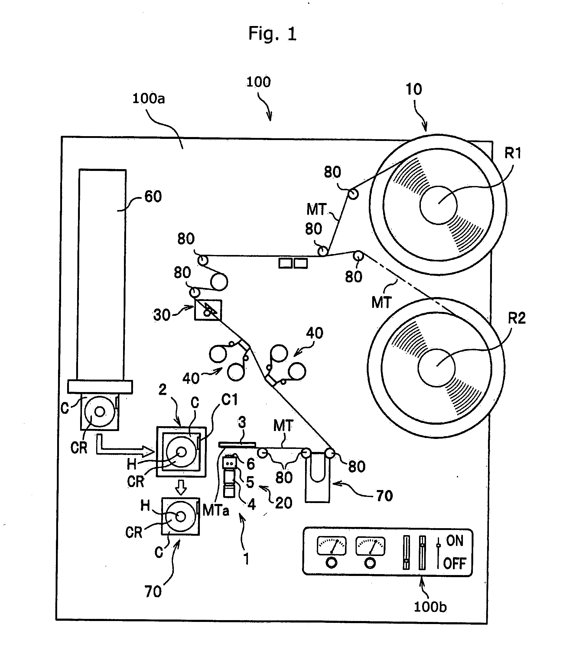
[0028] Referring now to the accompanying drawings in detail, FIG. 1 is a schematic view showing a tape winding apparatus 100 for winding a magnetic tape strip MT onto a reel hub H of a tape reel CR in an empty tape cartridge C. As shown in FIG. 1, the tape winding apparatus 100 winds a predetermined length of magnetic tape strip MT on the reel hub H installed in the cartridge case C. The predetermined length of magnetic tape strip MT is prepared by cutting a magnetic tape stock rolled in the shape like a pancake into rolls of magnetic tape strips MT, each roll having a given tape width, and by cutting the magnetic tape strip MT in a roll into the predetermined l...


PUM


Abstract

A tape end sticking apparatus sticking a tape end of a tape strip on a reel hub of a tape reel installed in a cartridge case having an egress / ingress opening before winding the tape strip onto the reel hub is described. The tape end sticking apparatus includes a tape carrier for grasping a tape end portion and bringing the tape end portion in close proximity to the reel hub which is movable into and out from a tape cartridge case through a cartridge opening and a liquid applying device for applying a sticking liquid to the reel hub and / or the tape end portion in a spread pattern having a width smaller at a remotest end than a foremost end thereof when the tape end sticking apparatus brings the tape end portion in close proximity to the reel hub.

Description

BACKGROUND OF THE ION [0001] 1. Field of the invention [0002] The present invention relates to a method of and an apparatus for attaching a tape strip end of magnetic tape strip on a reel hub of a tape reel in an empty tape cartridge and a method of and an apparatus for winding a tape strip onto a tape reel in an empty tape cartridge. [0003] 2. Description of Related Art [0004] Typically, magnetic tape cartridges are commonly used as an external memory device for computer data backup. Such a magnetic tape cartridge comprises a cartridge case, a tape reel and its associated parts enclosed in the cartridge case. The cartridge case has a tape egress / ingress opening located in one of end walls. In a final stage of a cartridge case production line, a magnetic tape strip is wound onto a tape reel in the cartridge case. Tape winding is entered by firmly sticking a tape end of the magnetic tape strip on the reel hub using a tape sticking device. There have been proposed a variety of tape st...

Claims


Application Information

Patent Timeline
IPC IPC(8): B65H19/28
CPCG11B23/20G11B23/113
Inventor KUBOTA, KAZUO
Owner FUJIFILM CORP
Learn More