Method for making a micro-fluid ejection device

a technology of microfluid and ejection device, which is applied in the direction of recording apparatus, instruments, photomechanical apparatus, etc., can solve the problems of relatively smooth planarization layer and substantially unchanged, and achieve the effect of less aggressive techniques and improved product yield

Active Publication Date: 2007-11-08
FUNAI ELECTRIC CO LTD
View PDF9 Cites 0 Cited by
  • Summary
  • Abstract
  • Description
  • Claims
  • Application Information

AI Technical Summary

Benefits of technology

[0008] An advantage of certain embodiments described herein may be that select areas of the photoresist etch mask may be essentially completely removed from the substrate with less aggressive techniques. Also, the planarization layer is left relatively smooth and substantially unaltered after the dry etching process and removal of the photoresist etch mask layer. Unlike conventional techniques used to remove etch mask layers, the exemplary embodiments described herein provide removal of substantially all of the photoresist etch mask layer, leaving essentially no residue on critical components such as electrical bond pads thereby improving product yield.

Problems solved by technology

Also, the planarization layer is left relatively smooth and substantially unaltered after the dry etching process and removal of the photoresist etch mask layer.

Method used


Image

  • Method for making a micro-fluid ejection device
  • Method for making a micro-fluid ejection device
  • Method for making a micro-fluid ejection device

Examples


Embodiment Construction

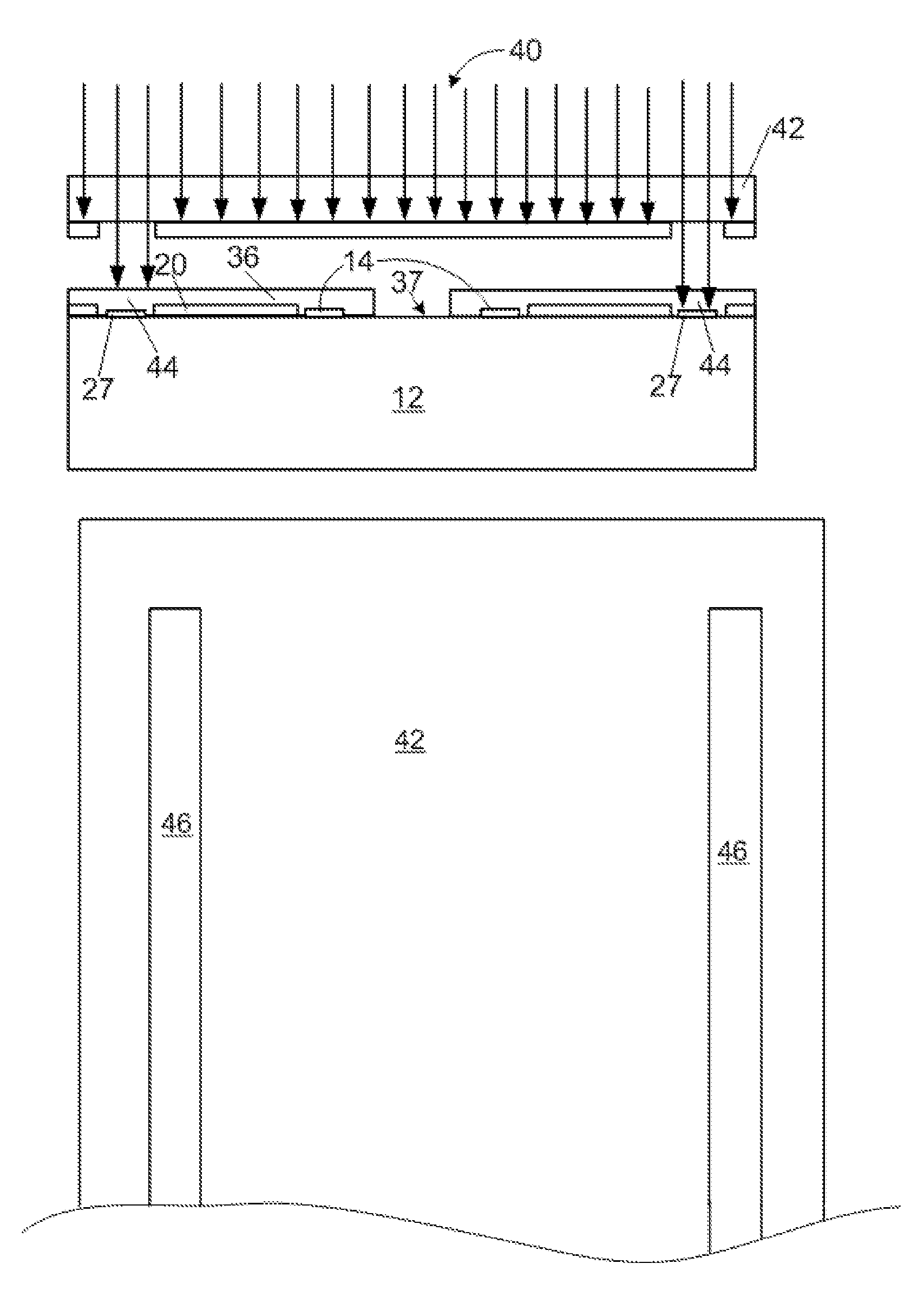
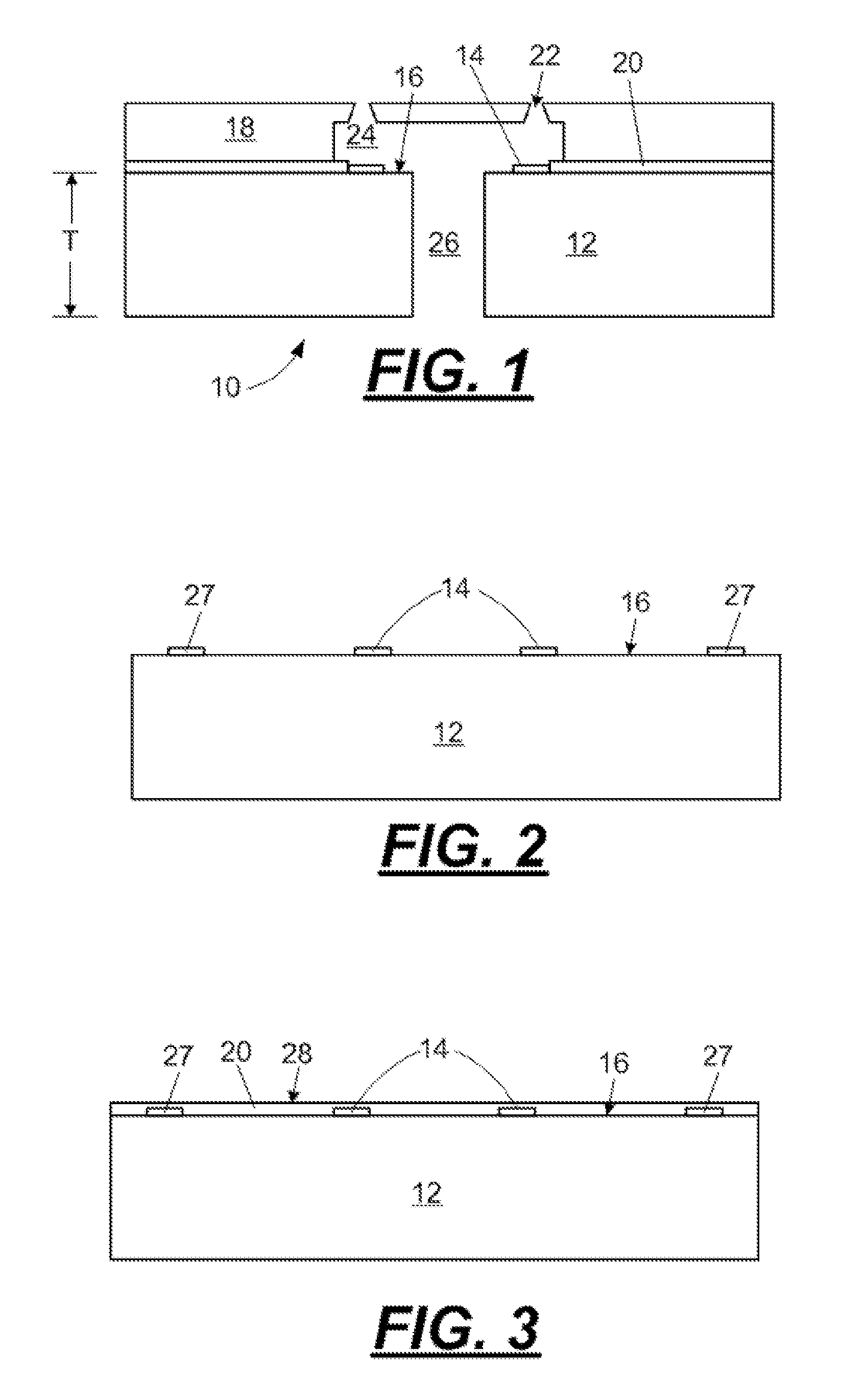
[0019] In one embodiment, there are provided methods for substantially removing an etch mask layer from a surface of a silicon substrate during a manufacturing process for making a semiconductor silicon chip used in micro-fluid ejection devices, such as ink jet printers. With reference to FIG. 1, a micro-fluid ejection head 10 for a micro-fluid ejection device such as an ink jet printer includes a semiconductor substrate 12, preferably made of silicon, having a thickness T. The substrate includes a plurality of fluid ejection devices such as heater resistors 14 on a device surface 16 thereof. The device surface 16 of the substrate 12 also includes various conductive, insulative and protective layers for electrically connecting the heater resistors 14 to a control device for ejecting fluid from the ejection head 10 and for protecting the resistors 14 from corrosion by contact with the fluid.

[0020] In order to provide a relatively planar surface for attaching a nozzle plate 18 to the...


PUM

PropertyMeasurementUnit
Lengthaaaaaaaaaa
Lengthaaaaaaaaaa
Lengthaaaaaaaaaa

Abstract

A method of etching a semiconductor substrate. The method includes the steps of applying a photoresist etch mask layer to a device surface of the substrate. A select first area of the photoresist etch mask is masked, imaged and developed. A select second area of the photoresist etch mask layer is irradiated to assist in post etch stripping of the etch mask layer from the select second area. The substrate is etched to form fluid supply slots through a thickness of the substrate. At least the select second area of the etch mask layer is removed from the substrate, whereby mask layer residue formed from the select second area of the etch mask layer is significantly reduced.

Description

[0001] This application is a continuation-in-part of application Ser. No. 10 / 803,009, filed on Mar. 17, 2004, now pending.FIELD OF THE DISCLOSURE [0002] The disclosure relates to micro-fluid ejection devices. More particularly, the disclosure relates an improved method for making micro-fluid ejection devices in order to increase the yield of usable product. BACKGROUND [0003] Micro-fluid ejection head such as used in ink jet printers are a key component of ink jet printer devices. The processes used to construct such micro-fluid ejection heads require precise and accurate techniques and measurements on a minute scale. Some steps in the ejection head construction process are necessary but can be damaging to the ejection head. Such damage to the ejection head affects the quality of fluid output, and, therefore, has an affect on the value of the ejection device containing the ejection head. [0004] One example of a technique that can result in such damage to an ejection head is the remov...

Claims


Application Information

Patent Timeline
IPC IPC(8): G03C5/00H01L21/461H01L21/302B41J2/16
CPCB41J2/1603B41J2/1628B81C1/00531B41J2/1645B81B2201/052B41J2/1631
Inventor KRAWCZYK, JOHN W.MRVOS, JAMES M.PATIL, GIRISH S.VANDERPOOL, JASON T.HART, BRIAN C.MONEY, CHRISTOPHER J.SINGH, JEANNE M. SALDANHAVAIDEESWARAN, KARTHIK
Owner FUNAI ELECTRIC CO LTD
Why Eureka
Try Eureka