Pulse wave modulator cutting assembly

a pulse wave modulator and cutting assembly technology, applied in the field of pulse wave modulator cutting assembly and cutting assembly, can solve the problems of significantly increasing manufacturing costs, low output, and more expensive processes such as pill manufacturing processes used to produce catalysts, and achieves improved cutting quality, reduced throughput, and increased production efficiency

Active Publication Date: 2007-11-08
JMP INDS
View PDF10 Cites 11 Cited by
  • Summary
  • Abstract
  • Description
  • Claims
  • Application Information

AI Technical Summary

Benefits of technology

[0005] The improved cutting assembly of the present invention is designed to cut a catalyst extruded from a die to form a cut product that more closely matches the desired L / D ratio of the catalyst, thereby eliminating the need for forming the catalysts by more expensive processes that have lower throughputs. The present invention also is directed to an extrusion cutting assembly which can increase the quantity of cut product while still producing a product having an L / D ratio which is significantly closer to the desired L / D ratio as compared to catalysts cut by prior art cutting assemblies.
[0006] The improved cutting assembly incorporates several new technologies that are used to produce a higher quality product. Each one of these new technologies individually result in increased product quality. In addition, the combination of these new technologies further increases the percentage for producing product having an acceptable L / D ratio. Prior cutting systems only results in about 15-35% of the cut product being within 200% of the desired length. The cutting assembly of the present invention results in about 60-99.9% of the cut product being within about 200% of the desired length, and typically about 70-99.9% of the cut product being within about 100% of the desired length. The cutting assembly of the present invention produces a higher quality product with significantly less waste. The cutting assembly of the present invention also has higher throughputs without sacrificing product quality.
[0007] One improvement of the cutting assembly includes the use of an increased number of wipers positioned closely adjacent to the openings in the die support plate. The wipers are used to direct material to be extruded into the openings for extrusion through the dies positioned in the openings. The wipers are also used to reduce or eliminate the amount of space around the openings that can harbor material, thereby reducing or eliminating the amount of material that stagnates or accumulates around the openings. Material that stagnates or accumulates around the openings can become hardened or less formable. This hardened or less formable material will eventually work its way into one of the openings. Due to the hardened or less formable nature of the material, the material can become stuck in the opening, thereby resulting in a clogged opening. The clogging of the opening reduces the number of dies that are used to form the extruded product, thereby reducing the amount of product being produced. The clogging of one or more dies also affects the pressure at which the material is extruded through the remaining unclogged openings. For instance, a plate which includes four openings would suddenly encounter a pressure increase of at least about 15-35% in the three unclogged openings when one of the openings becomes clogged. The increased pressure exerted on the extruded material results in the material being forced through the openings at an increased rate, thereby resulting in the lengths of the cut catalysts being increased when the cutting blade is running at a constant speed. The increased cut product typically results in an unacceptable product due to the unacceptably long product length, thus reducing the yield of acceptable product. The increased pressure on the material may adversely affect the material (i.e. adversely breaking down chemical bonds or structures, unacceptably increasing the heat applied to the material thereby resulting in adverse chemical reactions or structural formations, etc.). Such adverse affects on the extruded material can result in the material being unacceptable for its end use even if the cut length is within an acceptable range. The wiper blades of the improved cutting assembly are designed to reduce or eliminate the space about the openings that can harbor material to be extruded, thereby reducing or eliminating the incidence of one or more of the openings becoming clogged during an extruding process. The wiper blades are also used to reduce the pressure variations of the material being directed into the openings of the die holder. Typically, an auger is used to direct the material to be extruded toward the openings in the die holder plate. Most of these augers have a single flight configuration; however, dual flight configurations can be used. As the auger is rotated, the material to be extruded is moved toward the openings in the die holder plate. An opening in the die holder plate that is positioned closest to the face of the blade of the auger at a certain time is exposed to a higher pressure by the material than another opening on the die holder plate which is positioned at a farther distance from the blade face of the auger. As a result, when the auger is rotated during the operation, the pressure being applied to the extruded material at a particular opening increased as the face of the blade approaches a particular opening in the die holder plate and then decreases after the face of the blade passes the opening and moves to another opening as the auger rotates. The increasing and decreasing pressure being exerted on the material through the opening results in the material being accelerated and decelerated through the openings as the auger rotates. The increased speed at which the material passes through an opening results in an increased length of the material being cut when the cutter blade is rotated at a constant speed. The reduced speed at which material passes through an opening results in a reduced length of material being cut when the cutter blade is rotated at a constant speed. As a result, the cut material constantly varies in length due in part to the rotation of the auger feeding the material to be extruded through the die plates. The use of multiple wiper blades positioned between the end of the auger and the openings in the die holder plate results in a reduction of the pressure amplitude differential between a high and low pressure situation, thereby resulting in a more constant pressure being applied to the material directed into the plurality of openings in the die holder plate. As a result, the length of the cut material is more uniform due to the relatively constant pressure being applied on the material at all the openings in the die holder plate, thereby resulting in a higher percentage of acceptable product being produced. In one particular design, the number of wiper blades used in the improved cutting assembly is equal to or greater than the number of openings in the die holder plate. As can be appreciated, the number of wiper blades can be less than the number of openings in the die holder plate and still result in an improvement in the percentage of acceptable product. Typically, the wiper blades are connected to the end of the auger and are positioned closely adjacent to the openings in the die holder plate so as to reduce the amount of area about an opening which can harbor stagnant material. In another and / or alternative design, the wiper blades are sized so that they are at least as large as the openings in the die holder plate so as to facilitate in directing material into the openings. In another particular design, the size of the wiper blades are no more than about 30% larger than the diameter of the openings in the die holder plate so as to reduce the amount of dead area about the opening when a particular wiper blade passes by and over the opening, thereby reducing the amount of stagnant material which can become entrapped or stagnant about the opening or within the wiper area. It has been found that by properly designing the wiper blades, the amount of cut product that is within 100% or less of the desired cut length improves from 25% based upon standard cutting apparatuses to at least about 80%. This significant improvement in the amount of acceptable product reduces the amount of product that must be disposed of due to the fact that the cut length is too long or short, thus having an unacceptable deviation from the desired L / D ratio.
[0008] Another and / or alternative improvement of the improved cutting assembly is an improved control arrangement which can vary the cutting blade speed to better account for the pressure differentials applied to the material being extruded through a die in a particular opening of the die holder plate. When the pressure on the extruded material increases, the material travels at a faster rate through the die. Conversely, when the pressure on the extruded material reduces, the extruded material passes at a slower rate through the die. By detecting the pressure of the material as it enters into one or more openings in the die holder plate, it can be determined whether the material is accelerating, decelerating, or maintaining a constant velocity through the die within the die holder plate. If it is detected that the pressure has decreased, the speed of the blade can be accordingly decreased. If it is found that the pressure of the material has increased, the speed of the blade can be accordingly increased. Furthermore, if it is found that the pressure is constant, the speed of the blade can be maintained as constant. As a result, the control of the blade speed used to cut the material that has been extruded through one or more dies can be controlled so as to maintain a desired cut length of the cut extruded material. The rate of increase or decrease of the blade speed can be linear or non-linear. In addition, the change in blade speed can be delayed to account for the time that the material enters into the opening in the die holder plate and passes through the die prior to being cut by the blade. In one particular design, a pulse width modulator control system is used to control the rate at which the cutting blade cuts the material being extruded from one or more dies. As can be appreciated, other control systems can be used. In another particular design, the number of cutting blades selected can be the same as the number of dies being used to extrude the material. The control of the blade speed with respect to the detected pressure can also be used to adjust the cutting blade speed to account for abnormalities in the feed rate of the material being extruded. For instance, when one or more of the openings for the extruded material is clogged, thereby resulting in a significant increase in pressure on the extruded material through the remaining unclogged openings, the velocity of the cutting blade can be increased to account for the increased speed at which the material is extruded through the remaining unclogged openings. In another and / or alternative situation, the pressure applied to the openings in the die holder plate varies due to the feeding of the material by the auger or other type of feeding device. Even if wiper blades are used to decrease the range of pressure fluctuations, the changes in pressure being applied to the material being extruded resulting in increased and decreased velocities through the dies. The detection of these pressure fluctuation can be used to increase and / or decrease the cutting blade speed to obtain more cut product having a length within an acceptable length. In another and / or alternative situation, the rate at which material is fed into a feeder (e.g. auger) can vary, thereby resulting in variable amounts of material being fed to the opening in the die holder plate. Reduced amounts of material in the feeder results in reduced pressure on the material that is ultimately fed through the openings in the die holder plate. Increased amounts of material in the feeder results in increased pressure on the material that is ultimately fed through the openings in the die holder plate. By detecting these increases and decreases in pressure, the speed of the cutting blade can be adjusted to obtain more cut product having a length within an acceptable range. By detecting the pressure being exerted on the material being directed into the openings, the cutting blade speed can be increased to account for the increased velocity of the material passing through the dies, or decreased to account for the decreased velocity of the material passing through the dies, thereby maintaining the desired cut length of the material being cut by the cutting blades.
[0009] The improved cutting assembly can also and / or alternatively include multiple operational modes. One mode can be a manual mode wherein the speed of the cutting blade is set and maintained at a substantially constant speed throughout an extrusion process. The improved cutting assembly can also include an automatic mode wherein the speed of the cutting blade is adjusted based upon the detected pressure of the material prior to and / or as it is being extruded through the die, the detected velocity of the material prior to, during, and / or after being extruded through the die, and / or detecting the actual and / or calculated length of the cut material. The improved cutting assembly can include one or more adjustable parameters to adjust the length of the extruded material being cut so as to obtain a desired L / D ratio of the cut material, calibrate the pressure so that the speed control for the cutting blade is properly adjusted based upon a particular pressure, adjust the delay so as to delay the adjustment of the speed of the cutting blade to account for the time period in which the material travels into and through a die, etc. The improved cutting assembly can include one or more detectors (camera, light sensor, radio frequency sensor, sound wave sensor, etc.) to monitor the length of the extruded material prior to, during, and / or after the cutting process. This monitored information can be used to provide data on the quality of the material being cut, the percentage of the material being cut that is within an acceptable length, and / or to control the speed of the cutting blade to better obtain a desired cut length of the material. As can be appreciated, the detection of the length of the cut material can be monitored at the location of the cutting blade and / or at some period after the material has been cut (e.g. when the cut material is being conveyed to a drying location, etc.). In such situations, a video monitor or other device can be used to monitor the material being cut and / or conveyed and a software program or other type of statistical device can be used to determine the length and / or the L / D ratio of the cut product and send such information to the controller to be used to adjust the speed of the blade based upon the determined length and / or L / D ratio for the cut catalyst. Such a closed loop system could be used to further simplify the control system (e.g. reduce the number of control switches an operator uses) and / or facilitate in obtaining the desired product quality.
[0010] The improved cutting assembly can also and / or alternatively include various features used to deactivate the cutting blade especially when one or more dies are being replaced. It is not uncommon that the dies have to be periodically replaced after a run. A run may be as short as a few minutes or as long as several days or months. When the dies are removed from the openings in the die holder plate, it is important not to inadvertently activate the cutting blades during such operation, wherein such operation could result in the damage to the blades. The improved cutting assembly of the present invention can include one or more detectors, switches, etc. which fully or partially deactivate one or more components of the cutting assembly during repair and / or maintenance of the cutting assembly so as to reduce or prevent damage to one or more components of the cutting assembly. The improved cutting assembly can be also ergonomically designed so as to facilitate in the operation of the cutting assembly and / or to facilitate in the repair and maintenance of the cutting assembly. In one design, the cutting assembly allows the operator to easily access various connectors, bolts, switches, etc. which are required for periodic operation and / or maintenance of the cutting assembly. As a result of this ergonomic design, the need for special tools is reduced or eliminated and / or the operation and / or maintenance of the cutting assembly is simplified, thereby reducing the time and / or cost of maintenance and repair.

Problems solved by technology

If the acceptable range for the L / D ratio of the catalysts was narrower, more expensive processes such as pill manufacturing processes were used to produce the catalysts.
Although the pill manufacturing processes produced a large percentage of catalyst having a desired L / D ratio, the pill manufacturing process has extremely slow throughputs, resulting in low output over time and significantly increased manufacturing costs.
Such high costs are cost prohibitive for many chemical processes.
Due to the hardened or less formable nature of the material, the material can become stuck in the opening, thereby resulting in a clogged opening.
The clogging of one or more dies also affects the pressure at which the material is extruded through the remaining unclogged openings.
The increased cut product typically results in an unacceptable product due to the unacceptably long product length, thus reducing the yield of acceptable product.
The increased pressure on the material may adversely affect the material (i.e. adversely breaking down chemical bonds or structures, unacceptably increasing the heat applied to the material thereby resulting in adverse chemical reactions or structural formations, etc.).
Such adverse affects on the extruded material can result in the material being unacceptable for its end use even if the cut length is within an acceptable range.
This significant improvement in the amount of acceptable product reduces the amount of product that must be disposed of due to the fact that the cut length is too long or short, thus having an unacceptable deviation from the desired L / D ratio.
Even if wiper blades are used to decrease the range of pressure fluctuations, the changes in pressure being applied to the material being extruded resulting in increased and decreased velocities through the dies.
Increased amounts of material in the feeder results in increased pressure on the material that is ultimately fed through the openings in the die holder plate.
When the dies are removed from the openings in the die holder plate, it is important not to inadvertently activate the cutting blades during such operation, wherein such operation could result in the damage to the blades.

Method used


Image

  • Pulse wave modulator cutting assembly
  • Pulse wave modulator cutting assembly
  • Pulse wave modulator cutting assembly

Examples


Embodiment Construction

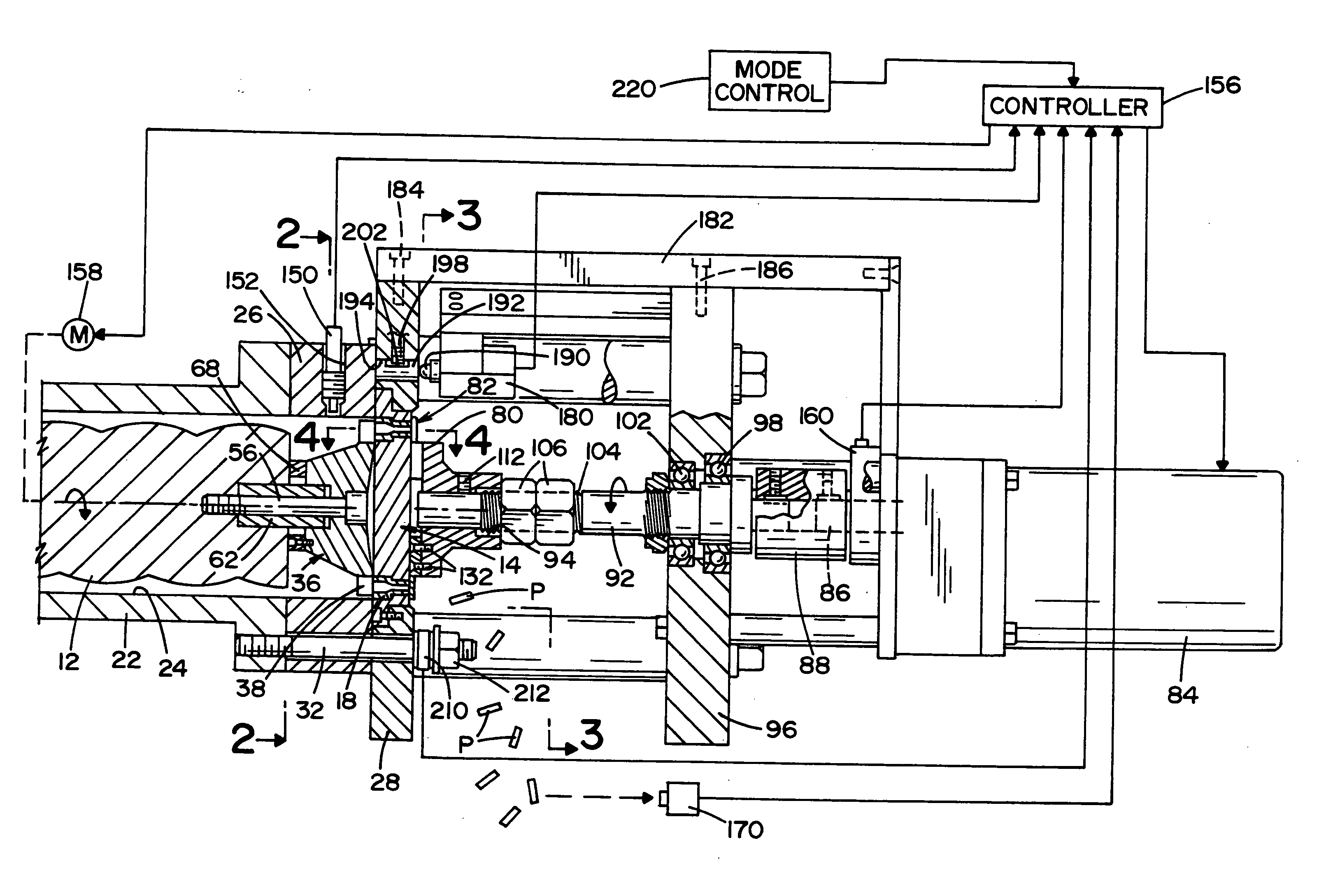
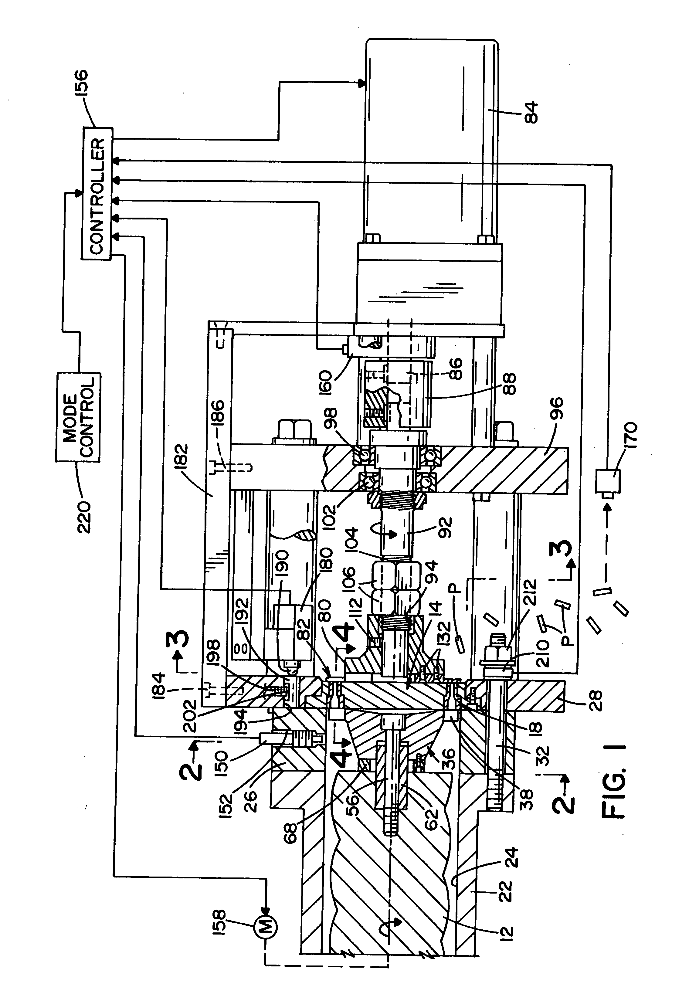
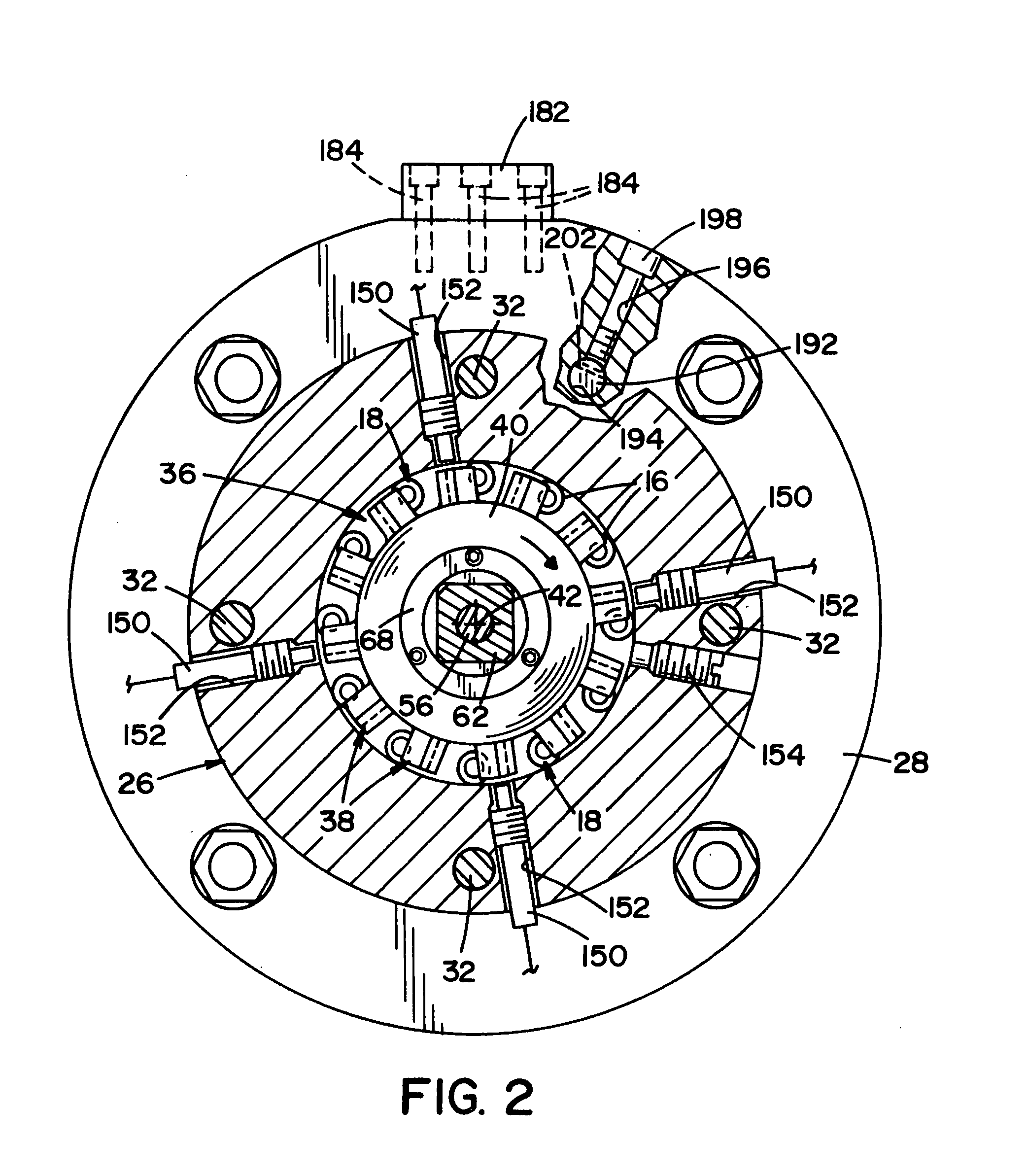
[0029] With reference to FIG. 1, an auger 12 moves material to be extruded toward a die plate 14 having a plurality of die openings 16 that receive dies 18. The material will become an extruded catalyst; however, the cutting assembly can be used to cut many other types of extruded material. The auger 12 is of the type known in the art and can, for example, have a single flight configuration or a dual flight configuration. The auger 12 is housed in an auger housing 22 that defines a cylindrical opening 24 through which the material to be extruded travels. The die plate 14, in the depicted embodiment, is a circular plate having the plurality of die openings 16 formed through the plate. The dies 18 depicted in the figures are shown in only one configuration for the sake of clarity only. The dies 18 can take numerous configurations that are known in the art.

[0030] An annular spacer 26 attaches to an end of the auger housing 22 and an annular die holder 28 attaches to the annular spacer...


PUM

PropertyMeasurementUnit
lengthaaaaaaaaaa
pressureaaaaaaaaaa
velocityaaaaaaaaaa

Abstract

A cutting assembly for cutting a material extruded from a die can include a wiper adapted to connect to an auger or a rotating member, a die holder plate disposed adjacent the wiper, a cutter member disposed downstream from the die holder plate, and a pressure sensor.

Description

[0001] This patent application is a continuation of U.S. patent application Ser. No. 11 / 062,220 filed Feb. 18, 2005, which in turn claims the benefit of U.S. provisional patent application Ser. No. 60 / 548,693, filed Feb. 27, 2004, which is incorporated by reference herein in its entirety.BACKGROUND OF THE INVENTION [0002] The present invention relates to extruder devices and more particularly to a cutting assembly to cut materials that have been extruded through a die. SUMMARY [0003] The present invention is directed to an improved cutting assembly used to cut materials that have been extruded through one or more dies. The cutting assembly of the present invention is particularly directed the cutting of extruded catalyst; however, the cutting assembly can be used to cut many other types of extruded material. [0004] The improved cutting assembly is designed to improve the product quality of cut extruded material by cutting the extruded material to a certain specified length. In the c...

Claims


Application Information

Patent Timeline
Patent Type & Authority Applications(United States)
IPC IPC(8): B29C47/36B29C69/00B29C48/04B29C48/05
CPCB26D7/2614B29B9/06B29C47/0014B29C47/003B29C47/0066B29C2947/92638B29C2793/0027B29C2793/009B29C2947/92019B29C2947/9258B29C2947/9259B29C47/30B29C48/05B29C48/12B29C48/0022B29C48/345B29C2948/92019B29C2948/9258B29C2948/9259B29C2948/92638B29C48/04
Inventor PINCHOT, JAMES M.
Owner JMP INDS
Why Eureka
Try Eureka