
Apparatus for managing requests for data in a communication network

a technology for communication networks and apparatus, applied in electrical apparatus, data switching networks, digital transmission, etc., can solve the problems of large amount of network resources required to carry unicast data, and delay or latency that is quite perceptible, so as to reduce the capacity of the predetermined request service device for handling data requests, reduce the traffic load on the network, and reduce the effect of data load

Inactive Publication Date: 2007-10-18
ALCATEL LUCENT SAS
View PDF24 Cites 23 Cited by
  • Summary
  • Abstract
  • Description
  • Claims
  • Application Information

AI Technical Summary

Benefits of technology

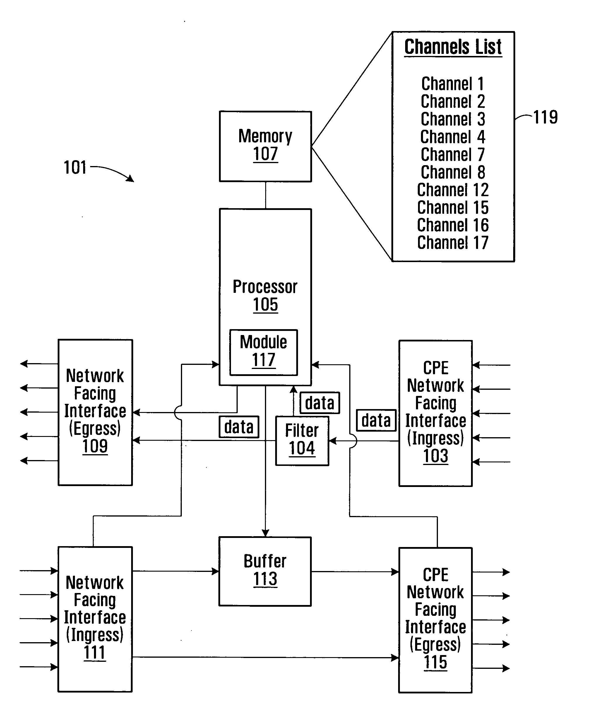
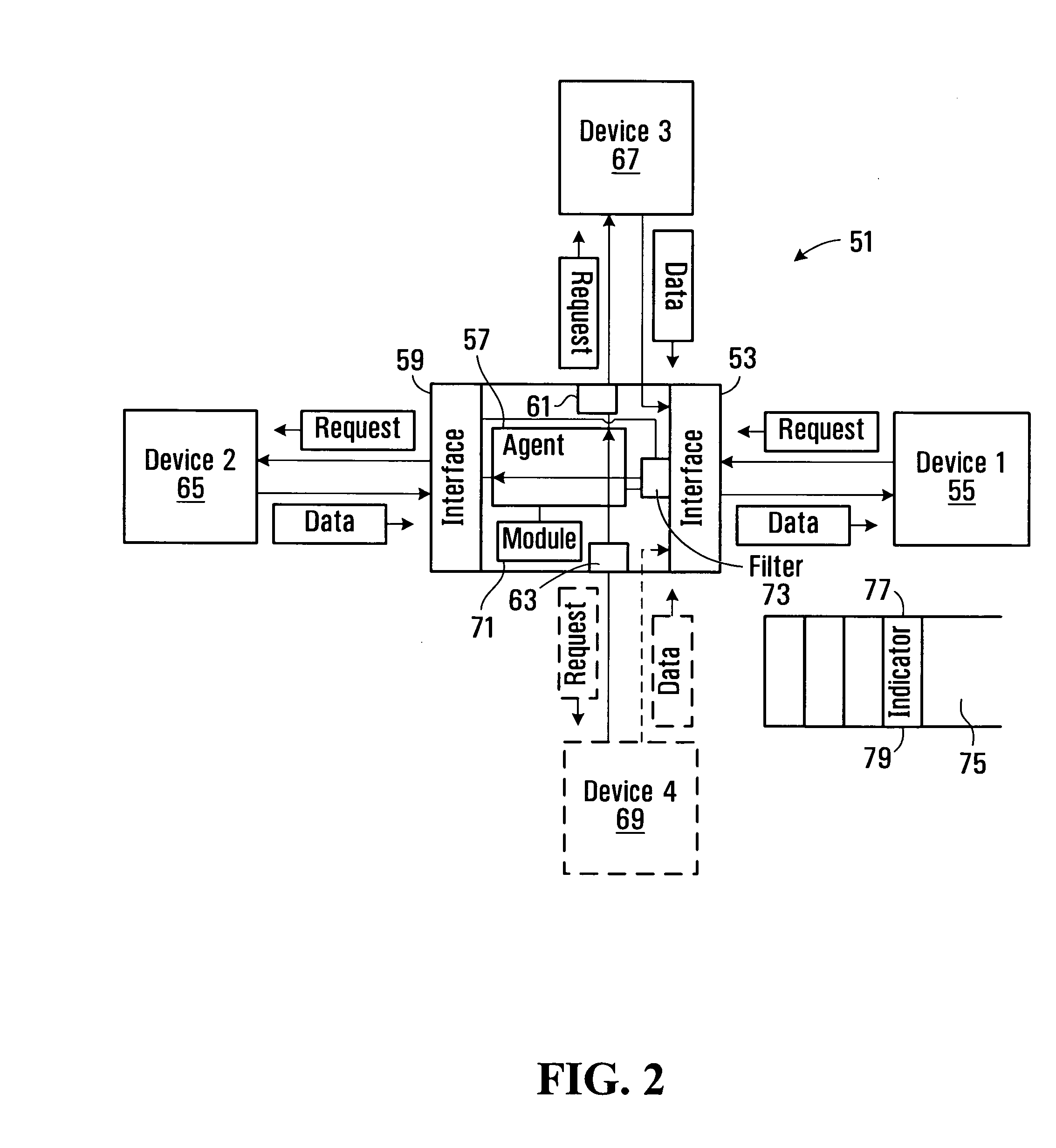
[0009] In this arrangement, an agent intercepts data that is addressed for processing by a predetermined entity and has the ability to redirect the data to another entity for processing the data. This arrangement allows data to be processed by a particular entity without the device from which the data is transmitted needing to specifically address the data to that particular entity. Therefore, redirection of the data by the agent and processing of the data by the other entity can both be transparent to the device from which the data is transmitted. In this arrangement, the agent and the other entity can operate entirely independently of the predetermined entity to which the data is addressed, and therefore operation of the agent and the other entity may be transparent to that predetermined entity. This arrangement also removes the need for the agent to be explicitly identified to any other device, such as the device to which the request is addressed or a system for managing that device or in which the apparatus may operate.
[0019] This arrangement provides flexibility in a system which is capable of handling data requests by enabling the device which services the request to be selected from a plurality of different service request devices based on their ability to handle the request. Thus for example, the predetermined request service device may be a preferred request service device for handling data requests, in which case the module may determine that the request is to be handled by that request service device if it is able to do so. However, if the module determines that the preferred request service device is unable to handle the request, the module causes the request to be forwarded to another request service device.
[0020] This arrangement may be implemented in a communication network for transporting media data to different subscribers and may be beneficial for implementing fast channel changes to reduce the traffic load on the network. For example, both the predetermined request service device and the other request service device may comprise devices for providing subscriber equipment with video data required for fast channel changes, with the predetermined request service device being situated closer to the subscriber equipment than the other device. For example, the predetermined request service device may be situated at an edge or aggregation node of the network, at an access node connected to individual subscriber premises, or a node between an aggregation node and access node, and the other request service device may be situated more remotely, for example at or near a network edge node, or in the network core. In this case, the module determines whether the predetermined request service device which is closer to the subscriber equipment can handle a received request, and if so, enables that request service device to service the request. If the request service device can handle the request, the data load on the network will be reduced as fewer network resources will be involved in servicing the request due to the proximity of the request service device to the subscriber equipment. On the other hand, the module provides a mechanism by which the request can alternatively be handled by another request service device if the predetermined request service device is unable to service the request, so that the request can still be handled by the system even if the preferred request service device is unable to do so, for example, because that device does not have the requested data, or does not have the capacity (e.g. egress bandwidth) to transmit the required unicast video (or other requested) data. This arrangement also allows the capacity of the predetermined request service device for handling data requests to be limited, and therefore the device to be implemented possibly more simply and at a lower cost.
[0022] In some embodiments, the apparatus further comprises a selector for identifying and selecting requests for data for the determination by the module from other signals received by the first interface. Thus for example, the selector may provide a filtering function for identifying data requests from other signals and may be adapted to pass only data requests to the module to increase the speed at which data requests can be handled.

Problems solved by technology

Therefore, the longer the time interval between successive GOPs, the longer the delay between requesting a video channel and the channel being displayed, and this delay or latency can be quite perceptible.
Typically, unicast data sources required for fast channel change are deployed some distance from the access node and a subscriber premises and therefore a significant amount of network resources may be required to carry the unicast data.
Furthermore, as a unicast data device provides unicast data to many different subscribers, the network resources may be required to transport a large amount of unicast data.
As channel changes may be concentrated at particular times of the day, for example at 30 minute or hourly intervals that coincide with the beginning and ending of programs, the network may be required to carry large amounts of unicast data at the same time, causing a significant burden and possibly even exceeding the network capacity.

Method used


Image

  • Apparatus for managing requests for data in a communication network
  • Apparatus for managing requests for data in a communication network
  • Apparatus for managing requests for data in a communication network

Examples


Embodiment Construction

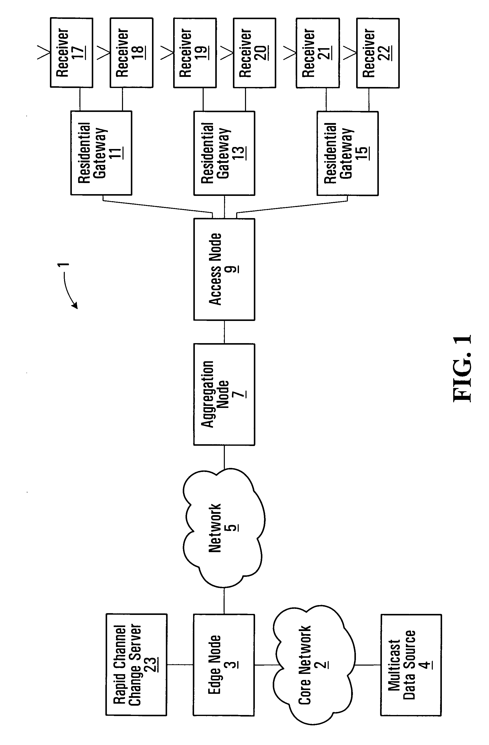
[0048]FIG. 1 shows an example of a network for providing IP services to a number of subscribers. The communication network generally shown at 1 comprises a core network 2 servicing edge nodes 3 (only one shown) for providing IP media services from one or more multicast data sources 4 (only one shown), a network 5 connected to the edge node 3, an aggregation node 7, and an access node 9 connected to the aggregation node and for delivering IP services to a number of different subscriber premises. This is an example of an end to end network, and there may be additional layers of physical devices, though FIG. 1 shows the basic functional blocks. In this example, the customer premises equipment (CPE) includes a residential gateway device 11, 13, 15 and one or more receiver(s) 17, 18, 19, 20, 21, 22 which may for example comprise a set top box for a television set, computer or other end user equipment. The access node may comprise, for example, a DSLAM (digital subscriber line access mult...


PUM


Abstract

An apparatus for managing requests for media data such as video data for effecting rapid channel change in IPTV services comprises an interface for receiving data requests addressed for processing by a particular data request service device, and an agent operatively coupled to the interface and configured for selecting which of a number of different data request service devices to send the request, irrespective of the device to which the request is addressed. The apparatus includes a module for determining if a received request can be serviced by a preferred request service device based on its monitored ability to service the request. If the module determines that the preferred device is capable of servicing the request, the request is directed to that device, and otherwise to another device, which may be the device to which the data request is originally addressed. The preferred request service device may reside at an access node for delivering media services to subscriber equipment.

Description

FIELD OF THE INVENTION [0001] The present invention relates to apparatus for managing requests for data in communication networks, and in particular, but not limited to apparatus for providing a user device with specific data from a media stream for enabling the device to rapidly start processing the media data. BACKGROUND [0002] In existing IP (Internet Protocol) TV broadcast networks, TV channels from one or more service providers are transmitted over the network to various access nodes located in residential or commercial neighborhoods and which provide a connection to each individual subscriber premises to provide selected TV channels and other services to subscriber equipment. [0003] Typically, the transmission media between the access node and the subscriber premises has limited bandwidth and may, for example, comprise a wire line such as a twisted copper pair. Each access node typically receives all of the channels to which customers connected to the access node subscribe. In...

Claims


Application Information

Patent Timeline
Patent Type & Authority Applications(United States)
IPC IPC(8): H04L12/56
CPCH04L29/06027H04L65/605H04L67/327H04L67/2814H04L65/4076H04L65/611H04L65/765H04L67/563H04L67/63H04L65/1101
Inventor BARRETT, TIMOTHY ALAN
Owner ALCATEL LUCENT SAS
Learn More