
Post anchor

a technology of post anchors and anchors, applied in the field of post anchors, can solve the problems of anchored posts rot, warp or corrode, and rainwater tends to run down the posts and collect, so as to reduce the chance of failure and limit the deformation of the post anchor

Active Publication Date: 2007-10-11
PEAK INNOVATIONS INC
View PDF72 Cites 29 Cited by
  • Summary
  • Abstract
  • Description
  • Claims
  • Application Information

AI Technical Summary

Benefits of technology

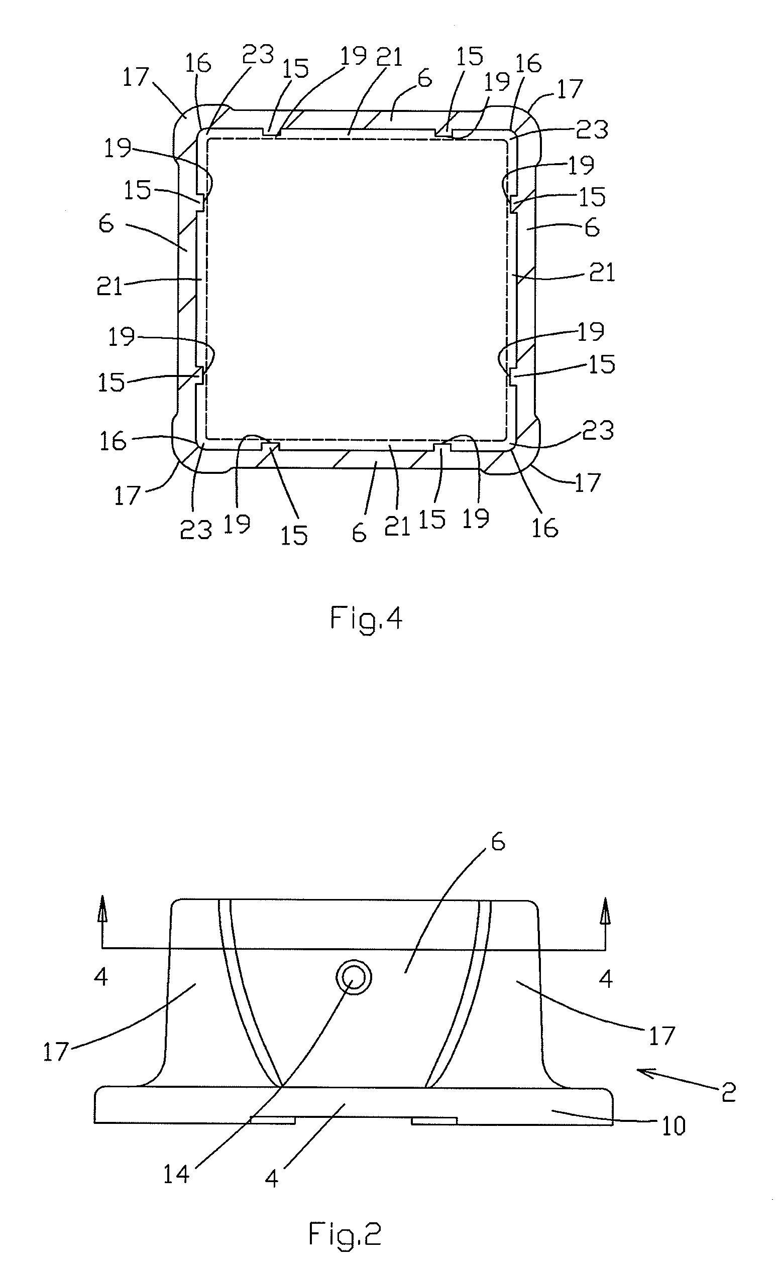
[0012] In yet another aspect of the invention, interior ribs extend medially along the vertical extent of each wall to limit deformation of the post anchor under pressure from the post as it expands.
[0013] In a further aspect of the invention, the corners of the post anchor may be thicker than the walls, thereby strengthening the post anchor and reducing the chance of failure due to expansion of the post inside the post anchor.

Problems solved by technology

One difficulty encountered with prior art post anchors is that water, such as rainwater, tends to run down the post and collect at the base, inside and around the post anchor cavity.
Standing water or simply contact with wet ground around or inside the base of a post may cause the anchored post to rot, warp or corrode or may otherwise damage the post.
Damage to the post may then destabilize any structure supported by the post.
If the post anchor is made of metal, standing water inside or around the post anchor cavity may also corrode the base and sidewalls of the post anchor, eventually leading to failure and destabilization of the supported structure.
However, an additional difficulty with prior art post anchors is that, particularly in the case of a wood post, the post tends to absorb water and will accordingly swell, or the post may simply shorten and expand over time under the weight of the structure being supported.
This pressure may deform the post anchor, and may also cause any corrosion-resistant coating to crack.
Under repeated swelling cycles as the post gets wet, then dries off, the cracked corrosion-resistant coating will peel or flake off and the post anchor itself will also eventually fail.
Apart from the coating failure, a prior art post anchor may still fail under repeated post swelling cycles, due to fatigue in the post anchor material from the changes in pressure exerted by the post.
Exposure to elements besides water can also cause difficulties, as ultraviolet rays may cause the post anchor material to break down and eventually fail.

Method used


Image

  • Post anchor
  • Post anchor
  • Post anchor

Examples


Embodiment Construction

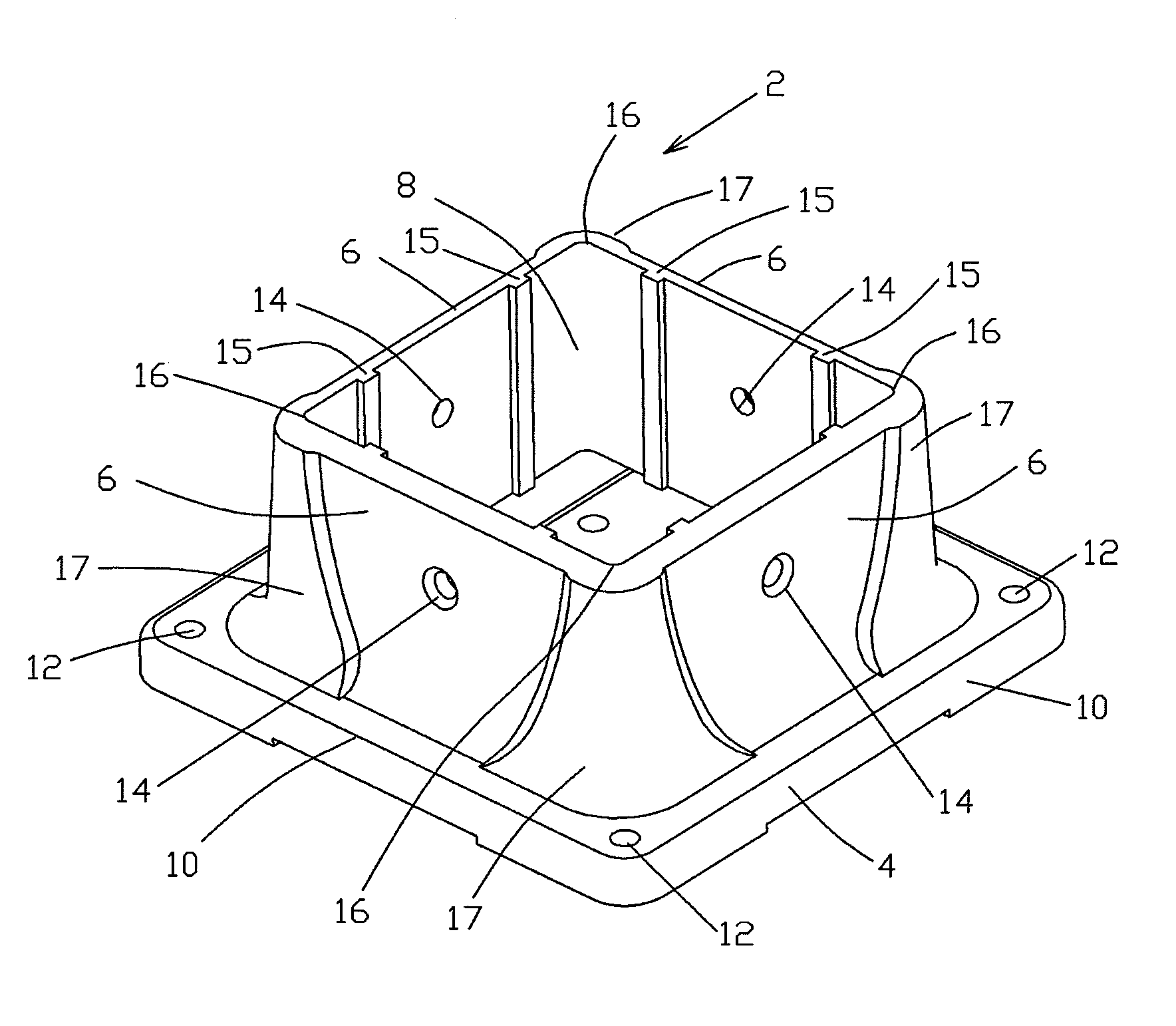
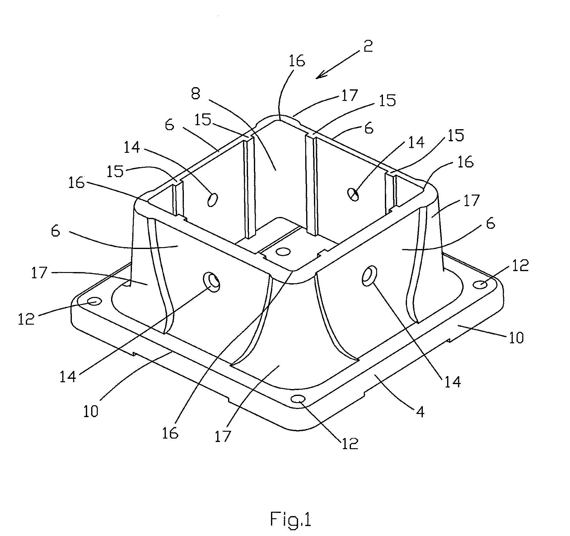
[0028]FIG. 1 is a perspective view of a preferred embodiment of the post anchor 2. The post anchor 2 is preferably made of a thermoplastic polymer, such as polyethylene, which is easy to form to the proper shape, corrosion-resistant, waterproof, strong, lightweight, and relatively inexpensive. The polyethylene surface can also be worked during the forming process to provide a rough, grainy texture, similar to the wood posts which the post anchor may support. Polyethylene is also available in many colours, which can be mixed to provide or enhance the appearance of an irregular, grainy surface, or otherwise selected to blend into the area where the post anchor is being used. Finally, polyethylene is easily modified to include additives, such as ultraviolet protectors, which may be useful for outdoor applications.

[0029] Post anchor 2 comprises a base 4, supporting four upstanding sidewalls 6, which define a cavity 8. Walls 6 may be placed anywhere on base 4, to provide a cavity 8 of v...


PUM


Abstract

A post anchor for securing a support post for a structure comprises a base with four upstanding sidewalls forming a cavity into which a post is inserted, and means to secure the post inside the cavity. Interior ribs and exterior augmented corners resist deformation under pressure exerted by the post. Interior channels allow water to drain from inside the cavity toward a drain hole. The anchor post is slightly elevated relative to the ground, allowing air and water to circulate around the post and post anchor. The post anchor is made of a thermoplastic polymer which is given a textured surface, and may include an ultraviolet protection additive.

Description

FIELD OF THE INVENTION [0001] This invention relates to post anchors of a type used to secure a support post for a structure, such as a deck, fence or other structure requiring vertical or horizontal support posts. BACKGROUND OF THE INVENTION [0002] One form of post anchor according to the prior art comprises a base with four upstanding sidewalls and means such as screws to attach the post anchor to a post within the cavity defined by the sidewalls. Such a post anchor is described in U.S. Pat. No. 6,729,089 issued May 4, 2004 to Spragg. [0003] One difficulty encountered with prior art post anchors is that water, such as rainwater, tends to run down the post and collect at the base, inside and around the post anchor cavity. Standing water or simply contact with wet ground around or inside the base of a post may cause the anchored post to rot, warp or corrode or may otherwise damage the post. Damage to the post may then destabilize any structure supported by the post. [0004] If the po...

Claims


Application Information

Patent Timeline
IPC IPC(8): A47B91/00
CPCE04H12/2269E04H12/2261
Inventor GROSS, JOHNWALKER, SIMONFAN, FRANKZHU, WEI MIN
Owner PEAK INNOVATIONS INC
Learn More