
Method for Displaying Bioinformation Using Millimeter-Wave Band Electromagnetic Wave, Device for Acquiring and Displaying Bioinformation

a technology of electromagnetic wave and electromagnetic wave, applied in the field of electromagnetic wave image analysis method and apparatus for living tissue, can solve the problems of low resolution, radiation damage to living tissue, and insufficient data for organisms, and achieve the effects of high speed diagnosis, efficient use of bioinformation, and appropriate medical diagnosis

Inactive Publication Date: 2007-10-04
INTPROP BANK CORP (JP)
View PDF11 Cites 15 Cited by
  • Summary
  • Abstract
  • Description
  • Claims
  • Application Information

AI Technical Summary

Benefits of technology

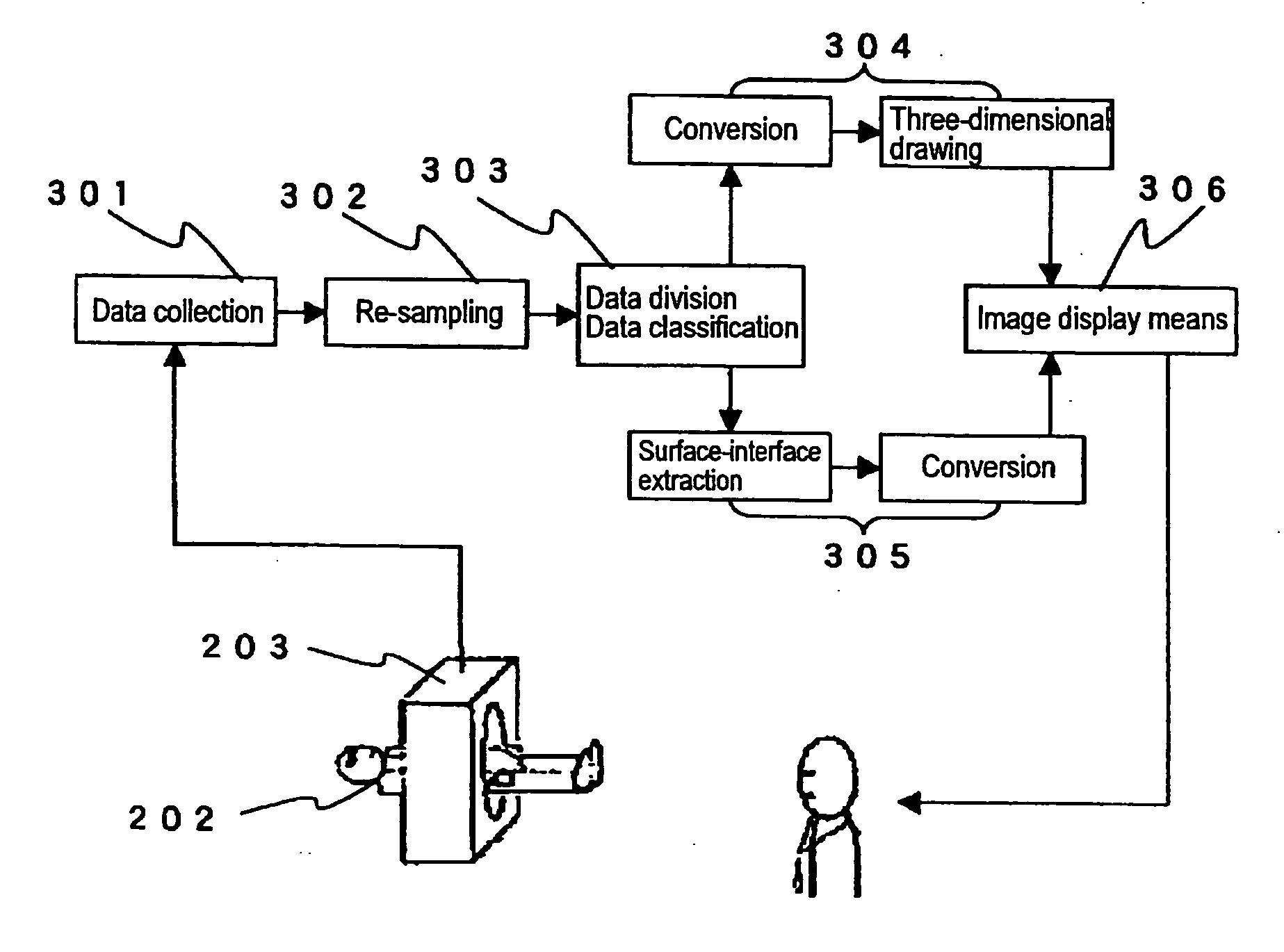
[0042] In contrast to bioinformation obtained by a bioinformation acquisition method using conventional electromagnetic wave region, qualitatively and quantitatively better useful bioinformation can be efficiently obtained by employing a millimeter-wave band electromagnetic wave, and thus more appropriate medical diagnosis is available. Furthermore, an image diagnostic method and apparatus are provided which enable high speed diagnosis at high resolution without causing radiation damage, thereby providing an effect of achieving low diagnosis cost. Furthermore, in an example of applying the present invention to cancer diagnosis, the diagnosis can be performed more reliably by means of diagnoses such as a high resolution three-dimensional image diagnosis, a high resolution cross-sectional image diagnosis, and a diagnosis by displaying an affected part with a color or the like applied thereto. Thus, an affected part in initial stage can be detected early, thereby providing an effect of facilitating treatment. FIG. 7 is an explanatory diagram for providing bioinformation for diagnosis by a doctor by means of an apparatus of an aspect of the present invention.

Problems solved by technology

However, at frequencies over 10 GHz, order of “mm” in wavelength, data for organisms has not yet been fully provided.
Hence, these conventional medical image diagnostic methods and apparatus have problems such as low resolution, giving radiation damage to living tissue, long diagnostic time, and high diagnostic cost due to high apparatus cost.
In addition to this, although the key of treatment is to detect initial variations early, it is very difficult to realize the early detection.
Thus, it has been very difficult to detect early initial variations of about several μm to about 1 mm.
However, the utilization of a millimeter electromagnetic wave for medical image imaging has not been disclosed since data for organisms has not yet fully provided as described above.
However, the measurement is performed only on a specific site of a human body, and thus the measurement is not performed on the entire human body two-dimensionally or three-dimensionally.

Method used


Image

  • Method for Displaying Bioinformation Using Millimeter-Wave Band Electromagnetic Wave, Device for Acquiring and Displaying Bioinformation
  • Method for Displaying Bioinformation Using Millimeter-Wave Band Electromagnetic Wave, Device for Acquiring and Displaying Bioinformation
  • Method for Displaying Bioinformation Using Millimeter-Wave Band Electromagnetic Wave, Device for Acquiring and Displaying Bioinformation

Examples


example 1

[0149] Hereinafter, for the radar medical diagnostic method and apparatus of the present invention, a detailed description will be given of another Example according to FIGS. 11 and 12.

[0150] An electromagnetic wave from an electromagnetic wave radiator of the analysis means provided with the electromagnetic wave application means and the electromagnetic wave reception means is a pulse electromagnetic wave having a duration of the applied electromagnetic wave of 0.1 nanoseconds to 10 nanoseconds and an interval between the pulses of 100 times to 10,000 times of the pulse duration and also is an electromagnetic wave having a single wavelength within the wavelength range of 6 mm to 12 mm. A reception sensor of the radar is a group of microwave sensor antennas. In order to reduce the load on a living specimen, the power of the radiator of the applied electromagnetic wave such as a variable wavelength microwave is lowered to the extent of not affecting the specimen and is about 10 kW o...

example 2

[0163]FIG. 15 is an example showing processing time when various computational methods for extracting an isosurface are applied to various measurement subjects. An MC method stands for a Marching Cube method and is a classical computational method. This is a method for drawing the shape of an isosurface of a measurement subject by finding voxels having the same intensity among adjacent voxels.

[0164] The structure of the computation is simple. However, the amount of the computation is huge, and thus a computer is required to have high performance.

[0165] An MB method stands for a Marching Boxes method. This is a computational method for drawing an isosurface by dividing an original solid body composed of solid data into groups of smaller unit cubes and sequentially merging a unit cube with an adjacent unit cube which has the same intensity as that of the former unit cube.

[0166] An Octree MB method is a computational method for performing detection of an isosurface at high speed, an...

example 3

[0168]FIG. 16 is a block diagram illustrating the structure of a computational method performed by the inventors and constructed on a UNIX (registered trademark) network to which computers such as SUN Sparc 1 are connected. The method is referred to as a DMC method (Distributed Marching Cubes method).

[0169] A program is divided to a master side 501 and slave sides 502. In the master side 501, a user interface, data collection, data decomposition, and the like are performed. In the slave sides 502, computation for an isosurface is performed, and the results are returned to the master side.

[0170] The master 501 determines the number of the slaves 502 to be employed according to the size of data. The slave 502 performs the MC method and a Phong model and returns the processing results to the master 501. The master 501 removes hidden surfaces by means of a z-buffer method and displays an image on a display.

[0171] In this Example, the MC method was employed as an extraction computatio...


PUM


Abstract

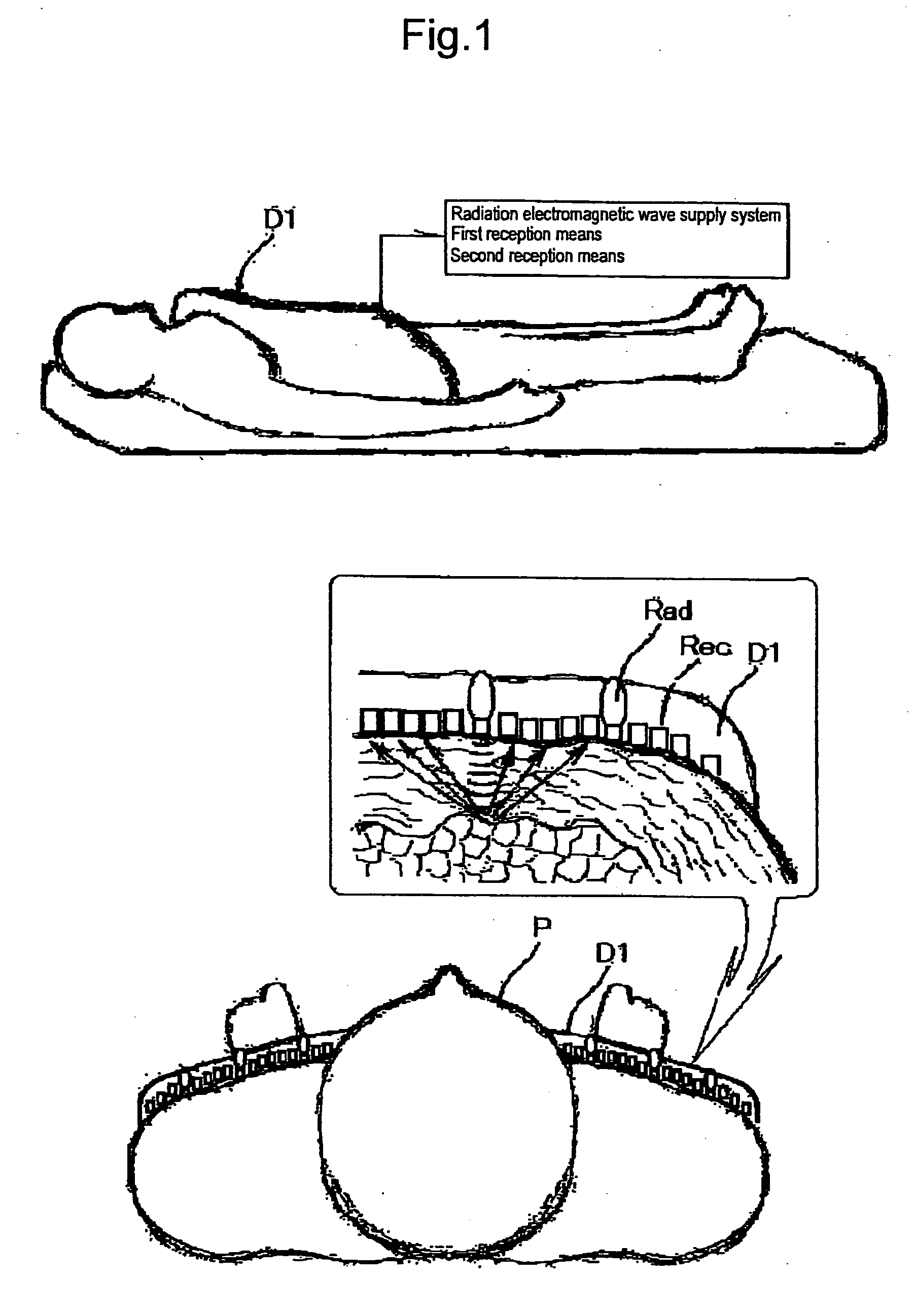
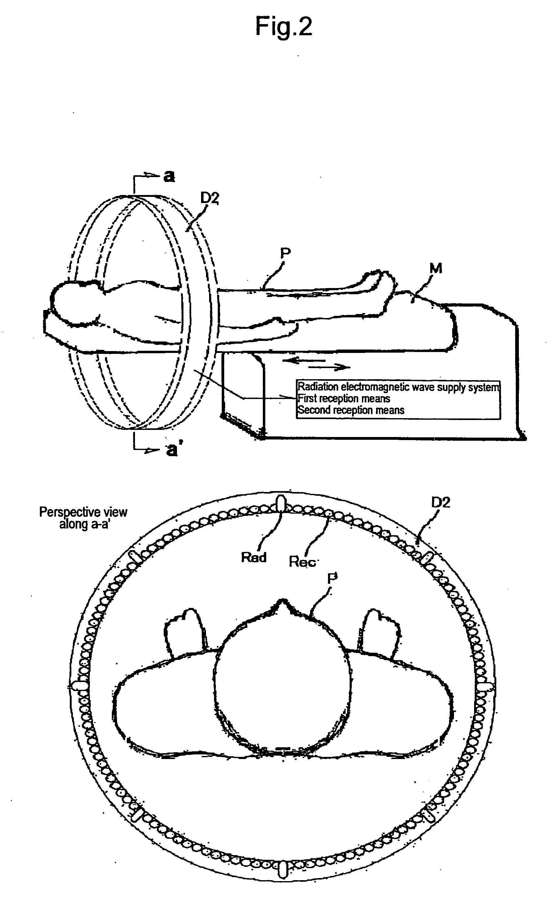
A method and device for extracting medically effective information by applying a millimeter-wave band electromagnetic wave to an organism and analyzing transmission, reflection and spontaneous radiation signals. The method and display comprise an acquiring step or means in which a database is so prepared in advance that from the transmission, reflection, and spontaneous electromagnetic wave data measured in a state that an organism is irradiated with an electromagnetic wave having wavelength components the wavelengths of which are 6 to 14 mm and a state that the organism is not irradiated, electromagnetic characteristics at the organism surface and in the organism is categorized and organized by actual condition of the organism constituent element, and the actual condition information on the organism constituent element of the subject is acquired according to the database information from the transmission, reflection, and spontaneous electromagnetic wave data measured in a state that the organism, the subject, is irradiated with a similar electromagnetic wave and a state that the organism is not irradiated; a step of associating the position information on the measurement portion of the subject with three-dimensional meridians and meridian points; and an image displaying step.

Description

TECHNICAL FIELD [0001] The present invention is an electromagnetic wave image analysis method and apparatus for living tissue. The electromagnetic wave image analysis method and apparatus are provided with two or more of at least one of the following analysis means: analysis means having means for applying an electromagnetic wave of millimeter wave range and means for receiving the transmission thereof, the reflection thereof, and spontaneous radiation; and analysis means not having means for applying an electromagnetic wave and composed only of reception means for receiving a spontaneous electromagnetic wave from a living tissue serving as a specimen. In the electromagnetic wave image analysis method and apparatus, signals from the abovementioned reception means are synthesized and image-processed by means of a computer having an appropriate interface to thereby be displayed, and thus abnormalities, a three-dimensional structure, a cross-sectional structure, a surface structure, or...

Claims


Application Information

Patent Timeline
Patent Type & Authority Applications(United States)
IPC IPC(8): G06K9/00
CPCA61B5/0507A61B5/05A61B10/00
Inventor IWAMATSU, SEIICHIMARUI, TOMOHIROKAWAGUCHI, NOBUAKISHINOZAKI, MAKOTO
Owner INTPROP BANK CORP (JP)
Learn More