
Temperature control apparatus for vehicle

a technology for controlling apparatus and vehicle, which is applied in the direction of indirect heat exchangers, lighting and heating apparatus, transportation and packaging, etc. it can solve the problems of difficult maintenance of the space in which to mount the hardboard, adversely affecting the appearance of the vehicle interior, and restricted location of the duct. achieve the effect of keeping the outer appearance attractiv

Inactive Publication Date: 2007-09-27
HONDA MOTOR CO LTD
View PDF28 Cites 8 Cited by
  • Summary
  • Abstract
  • Description
  • Claims
  • Application Information

AI Technical Summary

Benefits of technology

[0012]It is therefore an object of the present invention to provide a temperature control apparatus for a vehicle that can promptly heat a vehicle interior, that can be mounted uncomplicatedly in a side door, and that can keep the outer appearance looking attractive.
[0014]By virtue of the heat transmission mechanism, heat is transmitted effectively from the heat source to the heat pipe. Accordingly, the heat pipe can be favorably heated, heat from the pipe will be radiated to the vehicle interior, and a vehicle occupant will be promptly made comfortable.
[0015]Furthermore, in the present invention, the heat pipe is provided to the interior of the opening / closing member. Thus, the heat pipe is a member used solely for transmitting heat from the heat source and can be bent relatively freely. The heat pipe can readily be accommodated in a pre-existing space in the opening / closing member when the heat pipe is mounted on the opening / closing member. Thus, the heat pipe is provided to the interior of the opening / closing member, whereby the heat pipe is hidden from view by the opening / closing member, and the outward appearance of the opening / closing member remains attractive.
[0017]Desirably, the heat pipe is mounted on a lining using a mounting piece while the lining having the heat pipe is mounted on the opening / closing member. The process of assembling the opening / closing member and the lining is simplified.

Problems solved by technology

However, in the rear heater apparatus, the duct is provided to the inside surface of the sliding door and therefore adversely affects the appearance of the vehicle interior.
For this reason, when the duct is accommodated within the sliding door, the location where the duct is to be accommodated is restricted.
For this reason, a space in which to mount the hardboard is difficult to maintain in the side door, and considerable scope for improvement remains in this regard.

Method used


Image

  • Temperature control apparatus for vehicle
  • Temperature control apparatus for vehicle
  • Temperature control apparatus for vehicle

Examples


first embodiment

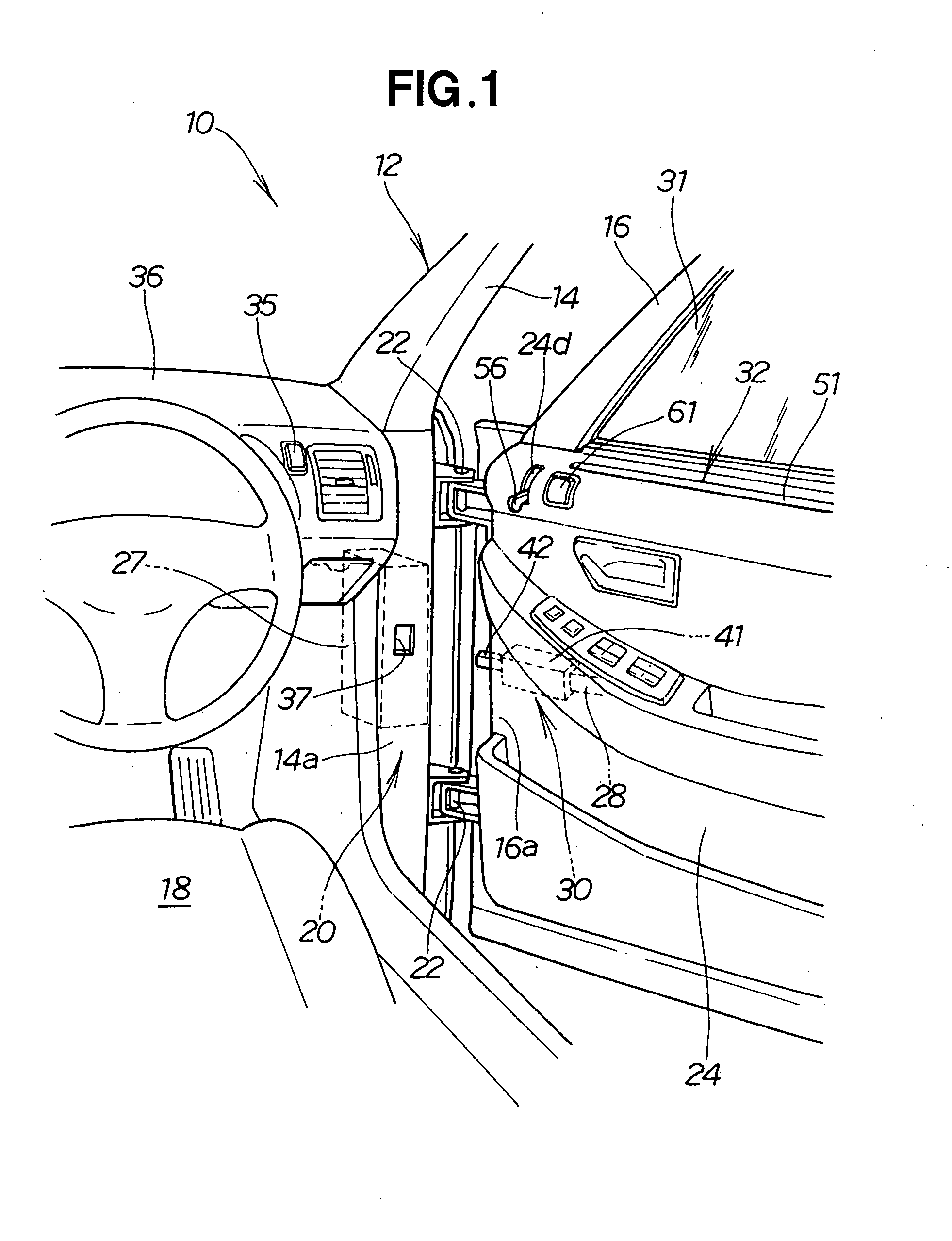
[0035]Reference is now made to FIGS. 1 through 5 showing a temperature control apparatus according to the present invention;

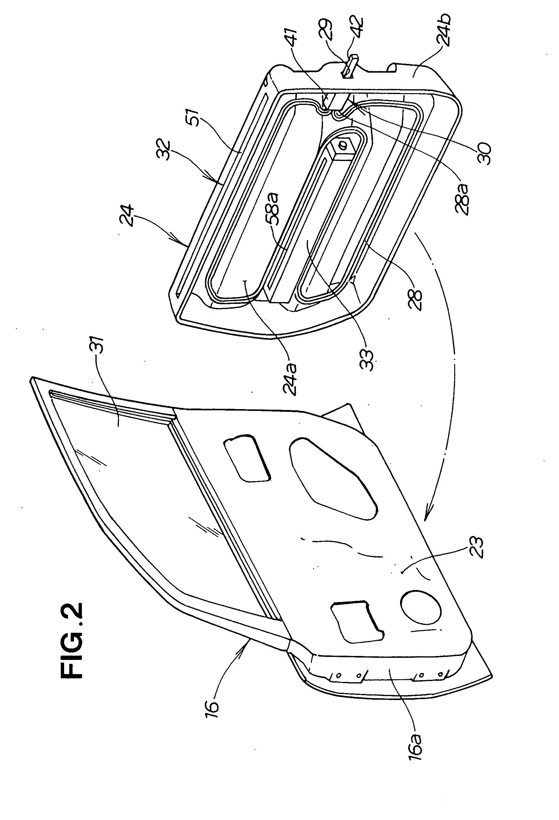
[0036]In FIGS. 1 and 2, a vehicle 10 has an opening 14 provided to a side part of a vehicle body 12, a side door (opening / closing member) 16 for opening and closing the opening 14, and a temperature control apparatus 20 for radiating heat from the side door 16 to a vehicle interior 18.

[0037]A front edge part 16a of the side door 16 is swingably mounted on a front edge part 14a of the opening 14 via upper and lower hinge members 22, 22. The side door 16 swings using the upper and lower hinge members 22, 22 as axes, whereby the opening 14 is opened and closed.

[0038]A lining 24 is provided to an inner panel 23 of the side door 16. The lining 24 is an interior finishing material that faces the vehicle interior 18 and that forms a wall part of the vehicle interior 18. A space 26 (FIG. 5) is formed between the inner panel 23 and the lining 24.

[0039]The temperature co...


PUM


Abstract

A temperature control apparatus for radiating heat from a side door to a vehicle interior is disclosed. A heat source is disposed within a peripheral edge part of an opening in a vehicle body. A heat pipe is provided to the side door. When the opening is closed by the side door, the heat source and heat pipe are thermally connected by a heat transmission mechanism.

Description

CROSS-REFERENCE TO RELATED APPLICATIONS[0001]The present application claims priority based on Japanese patent application 2006-086589, filed Mar. 27, 2006. The subject matter of this priority document, including specification, claims, and drawings, is incorporated by reference herein.FIELD OF THE INVENTION[0002]The present invention relates to a temperature control apparatus for a vehicle which is comprised of a body with an opening, and an opening / closing member capable of opening and closing actions relative to the opening.BACKGROUND OF THE INVENTION[0003]There are vehicles that have a rear heater apparatus, such as that disclosed in Japanese Patent Laid-Open Publication No. 11-129732, in which a diffusion outlet is provided to a sliding door formed on a central part of a side panel in the vehicle body, and hot air is blown out into a vehicle interior via the diffusion outlet.[0004]The rear heater apparatus has a heater unit provided to the side panel, a vehicle body-side duct tha...

Claims


Application Information

Patent Timeline
IPC IPC(8): B60H3/00F28D15/00
CPCB60H1/00271B60H1/243B60H1/247F28F2013/008F28D15/0266F28F13/00B60H2001/00221
Inventor HAYASHI, KENGOYAMAOKA, DAISUKE
Owner HONDA MOTOR CO LTD
Learn More