
Change-over apparatus for cooling gas passages in vacuum heat treating furnace

a vacuum heat treatment furnace and gas passage technology, which is applied in the direction of furnace cooling, muffle furnaces, furnaces, etc., can solve the problems of difficult stabilization of gas cooling, difficulty in smoothly actuating such damper units under affection, and insufficient cooling rate, so as to reduce the variation in opening area, less affection, and smooth change over gas passages

Active Publication Date: 2007-09-13
IHI CORP
View PDF4 Cites 10 Cited by
  • Summary
  • Abstract
  • Description
  • Claims
  • Application Information

AI Technical Summary

Benefits of technology

The present invention provides a cooling gas passage change-over apparatus for a vacuum heat treating furnace that can smoothly change over gas passages without being affected by wind pressure. The apparatus includes a stationary partition plate and a slidable shield plate that can alternately change the direction of gas passing through the cooling chamber. The slidable shield plate has a shield part that can partially shield the suction and discharge openings of the partition plate, ensuring stable gas cooling operation. The apparatus also has a simple structure, with a single drive to change the direction of gas passages, and a large opening area can be ensured. The cooling chamber is positioned so as to not affect the introduction and delivery of the article to be treated. The gas cooling and circulating system includes a cooling fan and upper and lower heat-exchangers to efficiently cool the gas flowing out and into the cooling chamber.

Problems solved by technology

However, early gas cooled vacuum heat treating furnaces were of depressurized cooling type, and accordingly, they offered such a disadvantage that its cooling rate cannot be sufficiently high.
However, in the case of the change-over mechanism employing the upward and downward gas passage, there have been arising problems as indicated below:
(1) Since the damper unit causes large variation in load depending upon its open and close positions, due to a wind pressure of gas which passes through these positions at a high speed, and accordingly, it is difficult to smoothly actuate such a damper unit under affection by the wind pressure in the case of a high pressure gas;
(2) Since the damper unit has such a configuration that an angle from its opening position to its closing position is not in proportion to its opening area, balancing between opening areas is difficult to obtain at the stage of changing over of a plurality of upper and lower drives so that a difference occurs between opening areas of a suction port and a discharge port, or the difference becomes large, and accordingly, the volume of cooling gas varies, resulting in making it difficult to stabilize gas cooling;
(3) Since there exist a plurality of upper and lower dampers, a plurality of drives is necessarily required, and accordingly, the structure of the mechanism becomes complicated; and

Method used


Image

  • Change-over apparatus for cooling gas passages in vacuum heat treating furnace
  • Change-over apparatus for cooling gas passages in vacuum heat treating furnace
  • Change-over apparatus for cooling gas passages in vacuum heat treating furnace

Examples


Embodiment Construction

[0036] A description of a preferred embodiment of the present invention will be provided hereinbelow, with reference to the accompanying drawings. Like reference numerals are used to denote like parts throughout the drawings in order to omit duplication of explanation thereto.

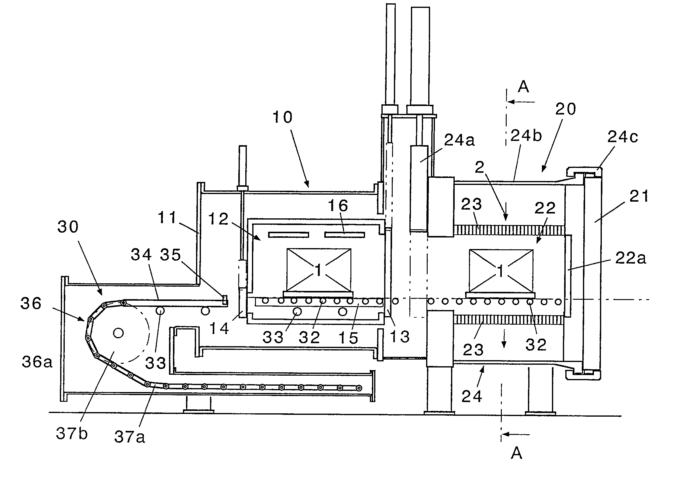
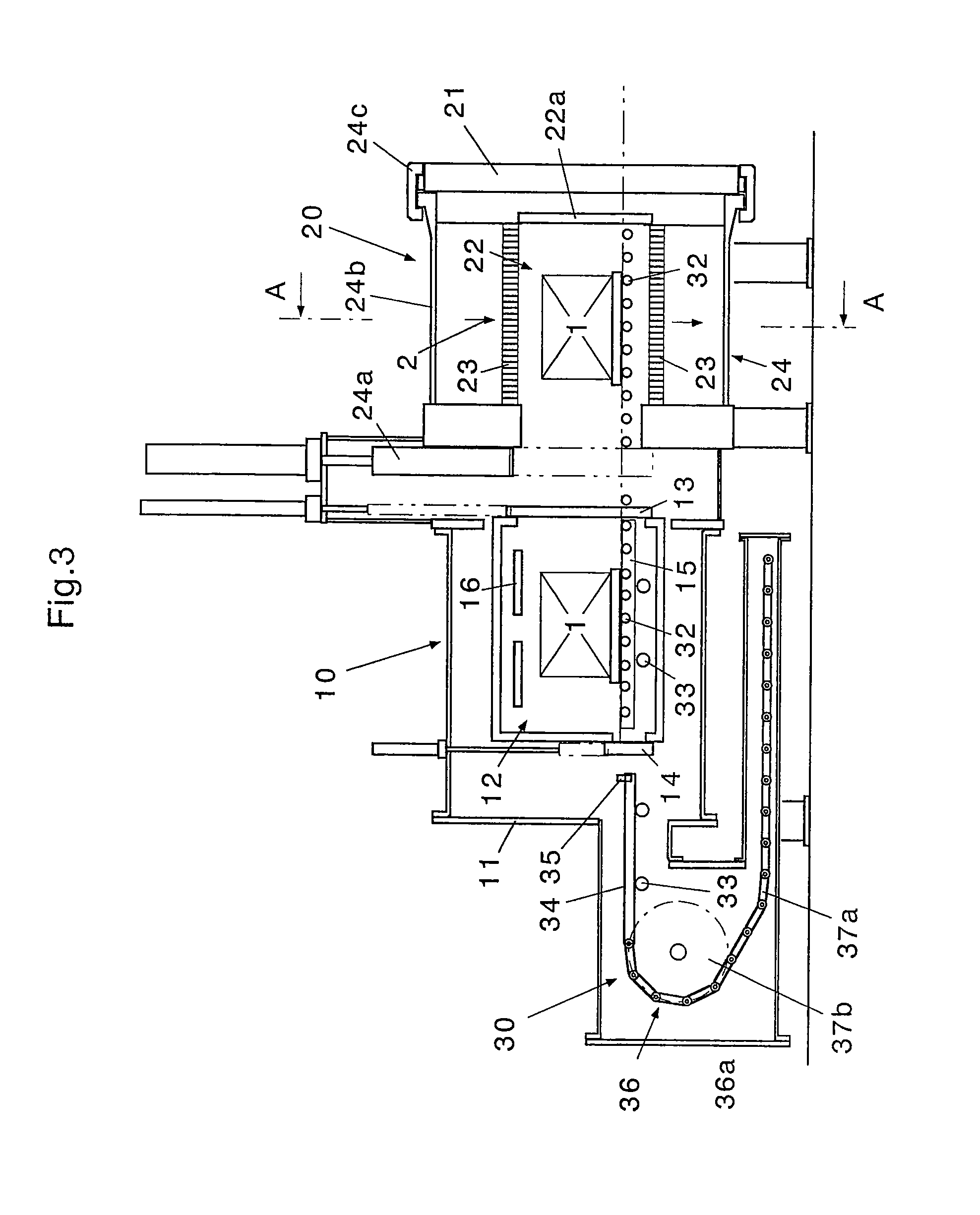
[0037] Referring to FIG. 3, which shows an overall configuration of a vacuum heat treating furnace provided therein with a change-over apparatus for cooling gas passages, according to the present invention, the vacuum heat treating furnace is a multiple chamber type heat treating furnace which is comprised of a vacuum heating furnace 10, a gas cooling furnace 20 and a shifting unit 30.

[0038] The vacuum heating furnace 10 is a sealable furnace arranged adjacent to a cooling chamber 22 in the gas cooling furnace 20 with a height which is equal to the cooling chamber 22, and incorporating a heating chamber 12 therein which heats an article 1 to be treated. The vacuum heating furnace 10 has a function capable of ...


PUM


Abstract

A change-over apparatus for cooling a gas passage is provided with a cooling chamber and a gas cooling and circulating system. The apparatus is further provided with a stationary partition plate and a slidable shield plate. The stationary partition plate has a suction opening and a discharge opening which are independently communicated respectively with a suction port and a discharge port, and the slidable shield plate has a shield part for partially shielding the suction opening and the discharge opening, whereby it is possible to alternately change over the direction of the gas passing through the cooling chamber.

Description

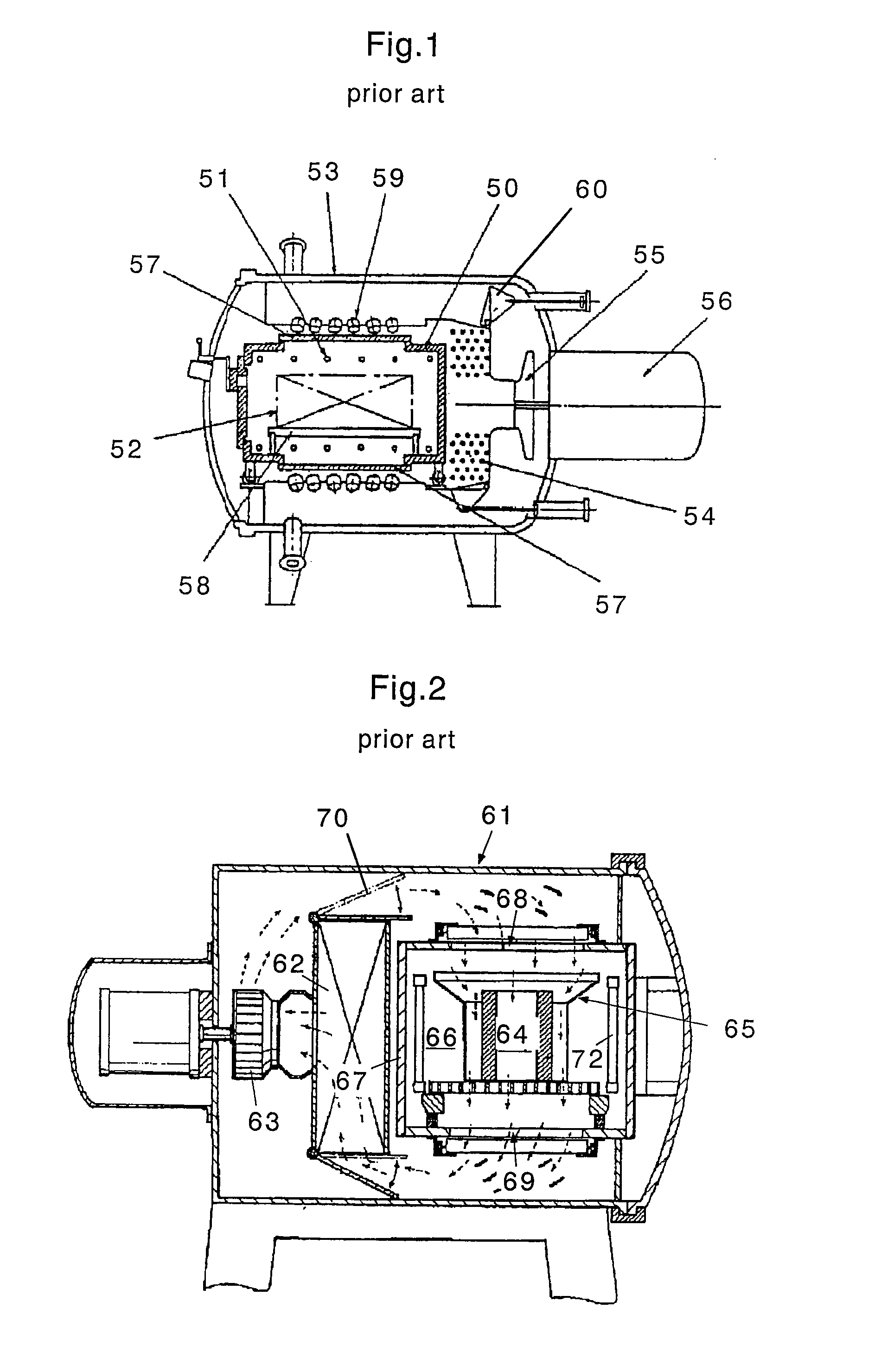
BACKGROUND OF THE INVENTION [0001] 1. Technical Field of the Invention [0002] The present invention relates to a change-over apparatus for changing over cooling gas passages in a vacuum heat treating furnace. [0003] 2. Description of the Related Art [0004] A vacuum heat treating furnace is the one in which inert gas or the like is refilled after depressurization of the inside thereof, in order to heat-treat an article to be treated. Since the vacuum heat treating furnace may completely remove moisture or the like sticking to the interior of the furnace and to the treated article after heating, by depressurizing again the furnace after evaporation of the moisture or the like, and by refilling the inert gas or the like thereinto, there may be exhibited such an merit that heat-treatment may be made without coloring by moisture (it is referred to as the “bright heat-treatment”). [0005] A gas-cooled vacuum heat treating furnace can exhibit several advantages as set forth in the following...

Claims


Application Information

Patent Timeline
Patent Type & Authority Applications(United States)
IPC IPC(8): F27D9/00
CPCF27B5/04F27B5/12F27D9/00F27B5/14F27B5/16F27B5/13
Inventor KATSUMATA, KAZUHIKONAKAHARA, TAKUHIRO
Owner IHI CORP
Learn More