
Replacement light fixture and lens assembly for same

a technology of replacement light fixture and lens assembly, which is applied in the field of replacement light fixture and a, can solve the problems of large brightness of the surface of the lamp compared to the size of the lamp, the discomfort of employing such lamps, and the severity of the brightness of the lamp. , to achieve the effect of increasing the light efficiency of the replacement, distributing light relatively uniformly, and reducing the cost of us

Active Publication Date: 2007-09-13
ABL IP HLDG
View PDF18 Cites 151 Cited by
  • Summary
  • Abstract
  • Description
  • Claims
  • Application Information

AI Technical Summary

Benefits of technology

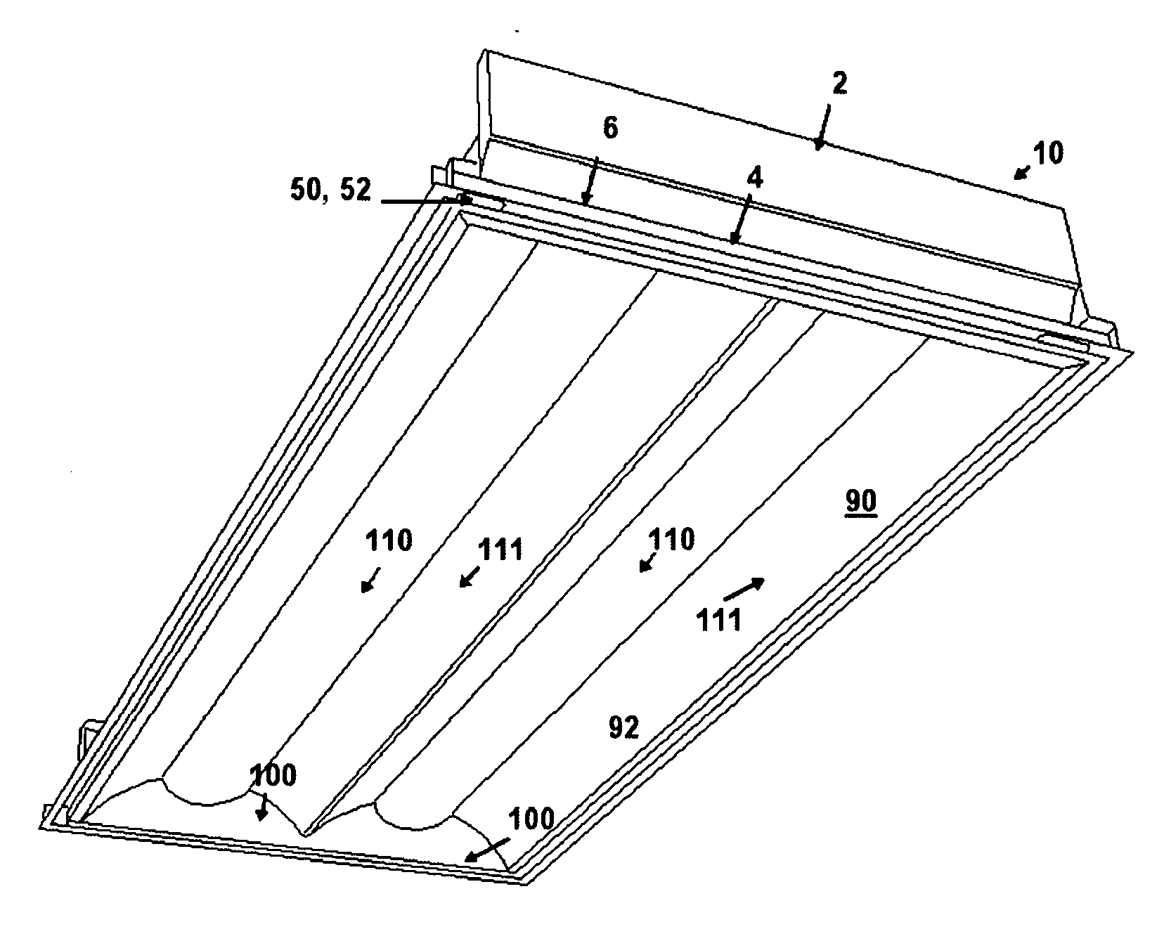
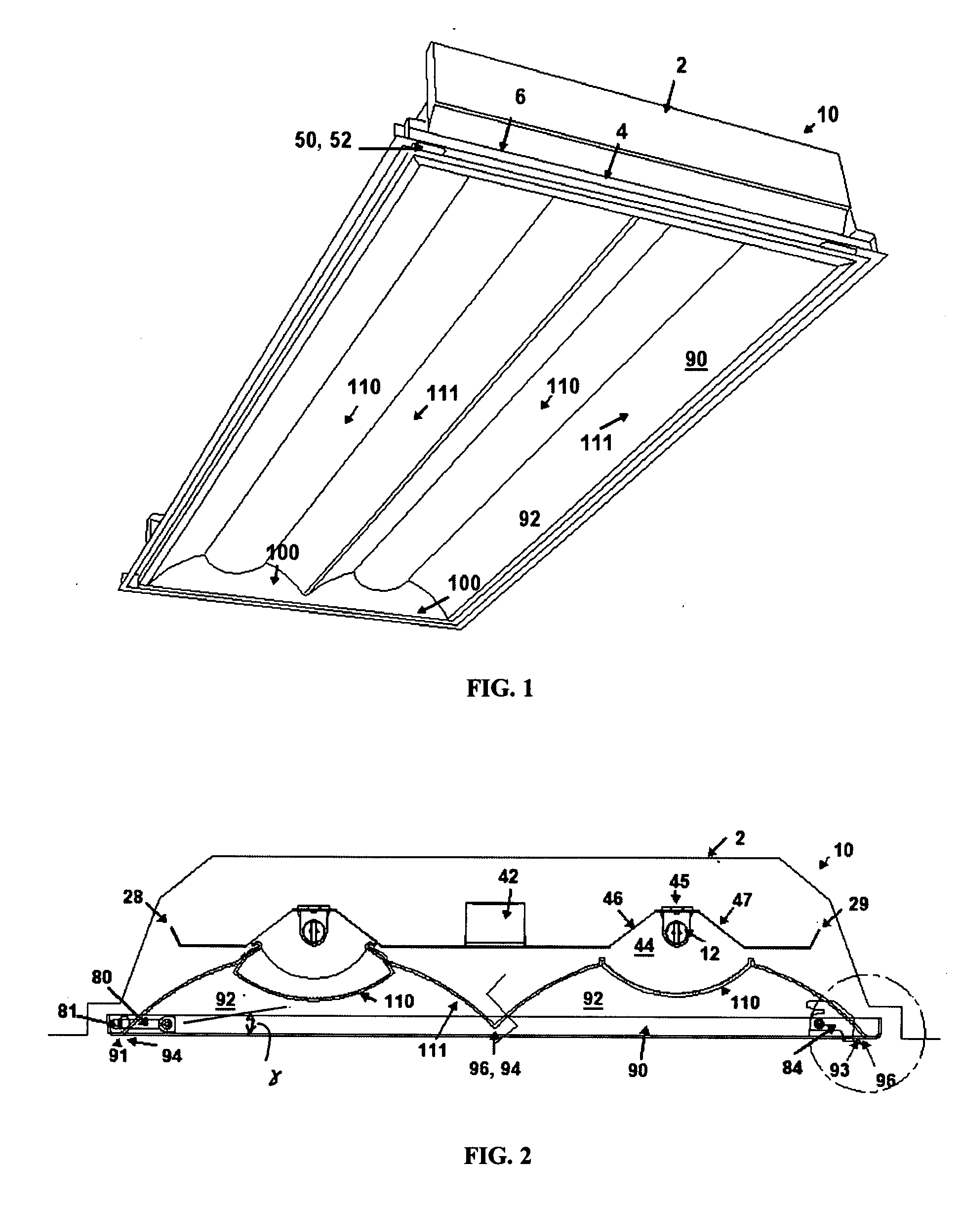
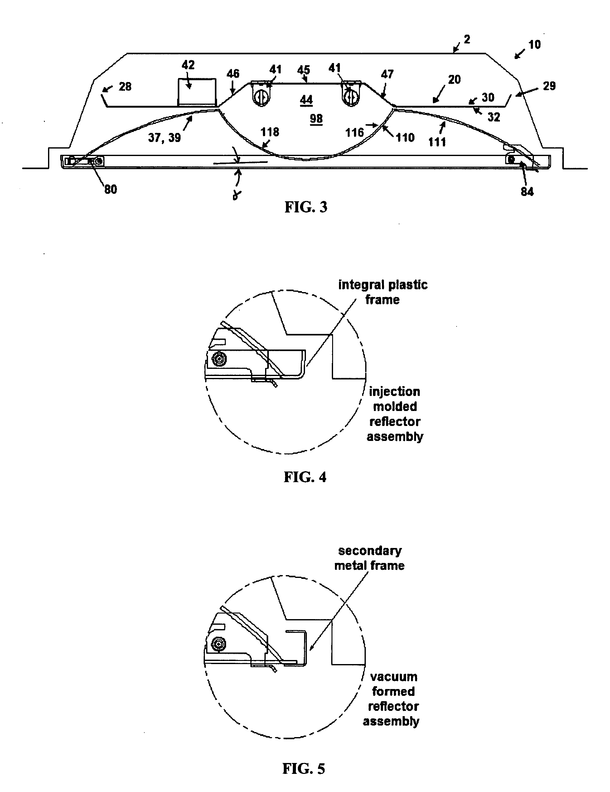
[0013] The present invention relates to a replacement or retrofit light fixture, or troffer, for efficiently distributing light emitted by a light source into an area to be illuminated. The lens and reflector of the present invention increase the light efficiency of the replacement or retrofit light fixture and diffuses the light relatively uniformly, which minimizes the “cave effect” commonly noted in areas using conventional parabolic light fixtures in the ceiling.
[0014] In one embodiment, suitable for retrofit or replacement applications, the present invention relates to a downlight light fixture for efficiently distributing light emitted by a light source into an area to be illuminated that can be mounted in a preexisting light fixture housing, which can be, in one aspect, conventionally mounted therein a ceiling.

Problems solved by technology

Some conventional fluorescent lamps, however, have the significant drawback in that the lamp surface is bright when compared to a lamp of larger diameter.
The consequence of such bright surfaces is quite severe in applications where the lamps may be viewed directly.
Without adequate shielding, fixtures employing such lamps are very uncomfortable and produce direct and reflected glare that impairs the comfort of the lighting environment.
Heretofore, opaque shielding has been devised to cover or substantially surround a fluorescent lamp to mitigate problems associated with light sources of high surface brightness; however, such shielding defeats the advantages of a fluorescent lamp in regions of distribution where the lamp's surfaces are not directly viewed or do not set up reflected glare patterns.
Thus, with conventional shielding designs, the distribution efficiencies and high lumen output advantages of the fluorescent lamp can be substantially lost.
A further disadvantage to traditional parabolic and prismatic troffers is the presence of distracting dynamic changes in brightness level and pattern as seen by a moving observer in the architectural space.
This unaesthetic condition is remedied by indirect and direct-indirect fixture designs, but typically with a significant loss of efficiency.
However, such design approaches have the drawback that the extra lamps impair the designer's ability to achieve a desired light distribution from a given physical envelope and impose added burdens on lamp maintenance providers who must stock and handle two different types of lamps.
One of these is reduced lighting efficiency.
Further, when viewed directly at high viewing angles, a conventional parabolic fixture can appear very dim or, even, off.
However, the newer technology lamps cannot be installed into existing fixtures as they require different lamp holders and ballasts.
Replacement of existing fixtures is very costly.
This option requires the purchase of completely new fixtures, wiring and construction costs of removing the old fixtures and installing the new fixtures, as well as the additional burden of the inconvenience and cost of closing down sections of the commercial structure as the construction proceeds.

Method used


Image

  • Replacement light fixture and lens assembly for same
  • Replacement light fixture and lens assembly for same
  • Replacement light fixture and lens assembly for same

Examples


first embodiment

[0148] Turning to FIGS. 23 and 25, an exemplary replacement light fixture 200 is illustrated. In this embodiment, the base housing 210 is coupled to the reflector assembly. After the louver, lamps, ballast and ballast cover of the preexisting light fixture are removed, the original, the preexisting lamp fixture housing 2 of the preexisting fixture remains mounted therein the ceiling. In this application, an edge of the base housing of the replacement light fixture is pivotally connected to an edge of the preexisting light fixture housing. In one example, one longitudinal edge of the base housing is pivotally connected, via a hinge, to a longitudinal edge of the preexisting light fixture housing. Alternatively, the respective end edges of the base housing and the preexisting light fixture housing are pivotally connected together. A means of selectively securing the base housing 210 of the replacement light fixture relative to the preexisting light fixture housing 2 is also provided s...

second embodiment

[0150] Referring now to FIGS. 26-28, a replacement light fixture is illustrated. In this exemplary embodiment, the base housing 210 of the replacement light fixture is connected to a portion of a preexisting light fixture housing. In one aspect, the base housing 210 of this embodiment has a first reflector piece 213 that overlies and partially surrounds the light source. The base housing further has a pair of opposing downwardly extending longitudinal side walls 214 that are symmetrically spaced from the longitudinal axis of the base housing. In one aspect, the ballast 42 is mounted to a portion of one of the downwardly extending side walls. In a further aspect, the base housing 210 is mounted to the preexisting light fixture housing such that the base housing extends substantially along the longitudinal axis of the preexisting light fixture housing 2.

[0151] The reflector assembly of the replacement light fixture 200 of this embodiment comprises a pair of opposing, complementary ref...

third embodiment

[0153] Referring now to FIGS. 29-34, the replacement light fixture of the present invention is disclosed. In this embodiment, the base housing 210 defines a pair of longitudinally extending and downwardly facing troughs 215. Each trough is configured to accept a longitudinally extending light source 12. In another aspect, the pair of troughs 215 is substantially parallel to each other. In another aspect, the base housing 210 further comprises a generally planar member 216 that extends between portions of the pair of longitudinally extending troughs 215 so that the longitudinal axis of the troughs are spaced a predetermined distance apart. The base housing 210 is configured to mount to a bottom surface of the preexisting light fixture housing so that the base housing is symmetrically positioned with respect to the preexisting light fixture housing.

[0154] In one aspect, the generally planer member 216 and portions of the opposing troughs 215 define a channel 217 forming an interior ca...


PUM


Abstract

A replacement light fixture for directing light emitted from a light source toward an area to be illuminated, including a base member upon with the light source is positioned and a reflector assembly detachably secured to a first and second mounting brackets that are mounted to a portion of the preexisting light fixture housing such that a lens portion of the reflector assembly overlies the light source and such that substantially all of the light emitted from the light source passes through the lens portion

Description

[0001] This application is a continuation-in-part of U.S. Utility patent application Ser. No. 10 / 970,615, filed on Oct. 21, 2004 and Ser. No. 10 / 970,625, filed on Oct. 21, 2004, which claim priority to U.S. Provisional Application No. 60 / 580,996, filed on Jun. 18, 2004, and claims priority to U.S. Provisional Application Nos. 60 / 722,231, filed on Feb. 10, 2006, and 60 / 860,671, filed on Nov. 22, 2006, all of which are incorporated in their entirety in this document by reference.FIELD OF THE INVENTION [0002] The present invention generally relates to light fixtures for illuminating architectural spaces. The invention has particular application in light fixtures using fluorescent lamps, such as the T5 linear fluorescent lamp, as the light source. More particularly, the invention relates to a replacement light fixture and a method of retrofitting preexisting recessed light fixtures. BACKGROUND ART [0003] Numerous light fixtures for architectural lighting applications are known. In the c...

Claims


Application Information

Patent Timeline
IPC IPC(8): F21V7/00
CPCF21S8/02F21S8/026F21S8/04F21V5/02F21V13/04F21Y2103/00F21V17/104F21V17/107F21V17/164F21V17/18F21V23/026F21V15/01
Inventor MAYFIELD, JOHN T. IIIGOULD, CARL T.MCILWRAITH, GEORGESHARP, CHRISTOPHER L.
Owner ABL IP HLDG
Learn More