Drizzle device

Inactive Publication Date: 2007-09-13
FUSIONBRANDS LLC
View PDF12 Cites 4 Cited by
  • Summary
  • Abstract
  • Description
  • Claims
  • Application Information

AI Technical Summary

Benefits of technology

[0010]The general purpose of the present invention, which will be described subsequently in greater detail, is to provide a device that facilitates both the drizzling of liquids and the extracting of dregs from hard to reach corners.
[0015]The second way is that once removal of the extracted content has been preformed the content held in the receptacle can be controlled by the user. Using a controlled amount of tilt applied to the receptacle nothing will pour from the receptacle until the tool is tilted. With a graduated increase or decrease of a tilting action the streaming out of the content from the receptacle gives the user the ability to increase or to limit the flow.
[0016]The third way is that the receptacle can pivot and then quickly return to its original position. This is important for being able to remove content, e.g., dregs, from containers of varying shape and size in the bottom hard to reach corners.
[0018]The present invention is comprised of a first part, a linear element, e.g. a shaft that on one end includes a handle, and on the opposing end includes a structure to provide some flexibility in the shaft. In one embodiment, the shaft is constructed out of a material that is not completely rigid but has some flexibility.

Problems solved by technology

If desired the user can remove the receptacle before it has had time to fill to its rim, thus limiting the amount for extraction.

Method used


Image

  • Drizzle device
  • Drizzle device
  • Drizzle device

Examples


Embodiment Construction

[0036]The present invention will now be described in detail with reference to a few preferred embodiments thereof as illustrated in the accompanying drawings. In the following description, numerous specific details are set forth in order to provide a thorough understanding of the present invention. It will be apparent, however, to one skilled in the art, that the present invention may be practiced without some or all of these specific details. In other instances, well known operations have not been described in detail so not to unnecessarily obscure the present invention.

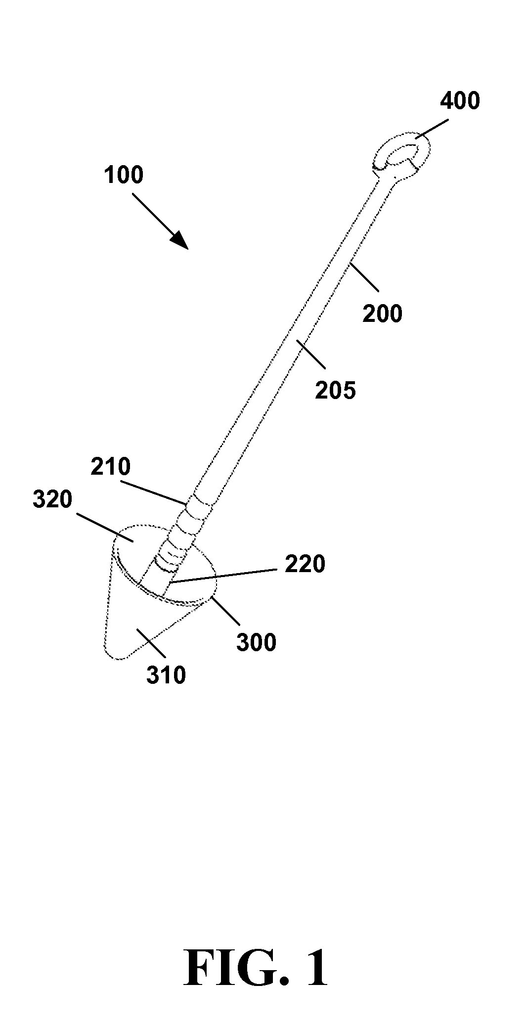
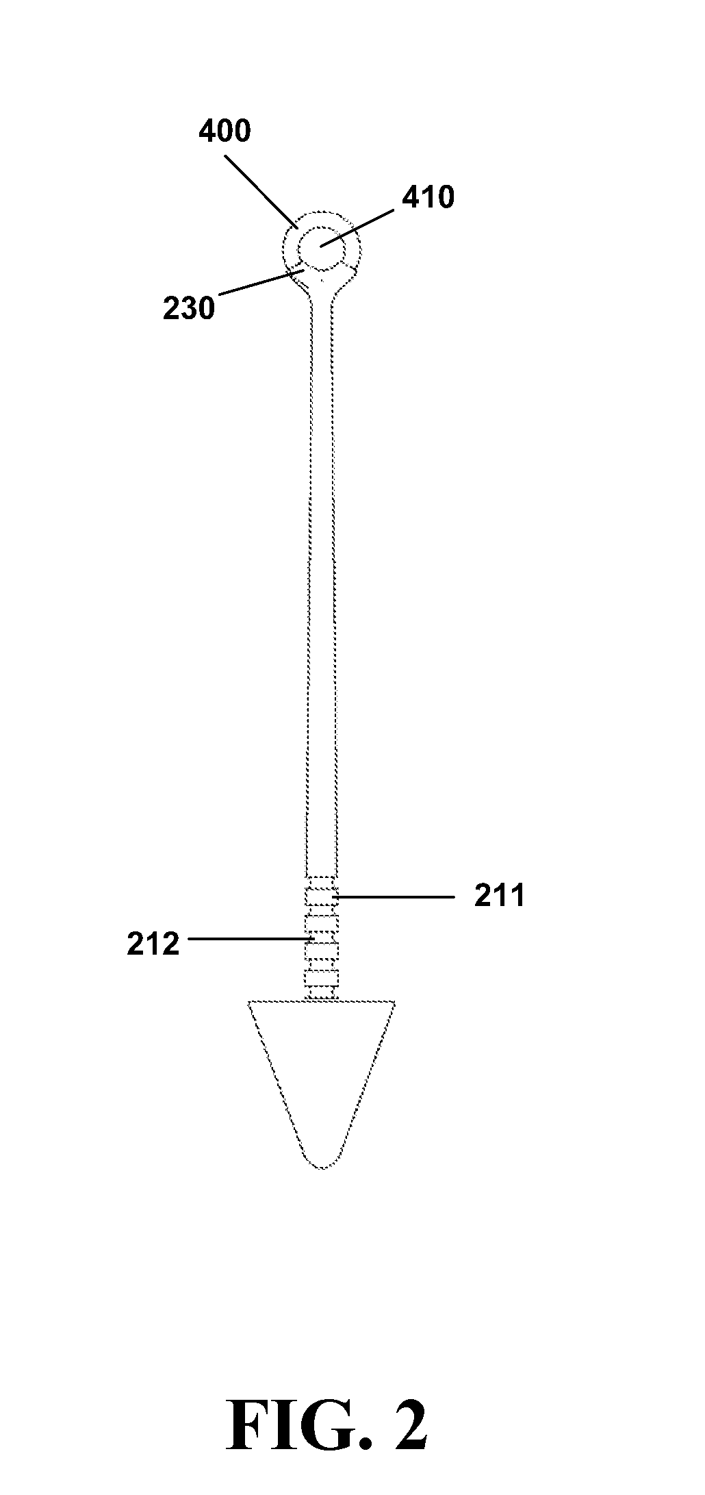
[0037]Referring now to FIG. 1 through FIG. 5 an embodiment of a drizzle device 100 is comprised of a handle portion 200 and a receptacle portion 300. The handle portion is comprised of a grip 205 that extends and connects to a flexing section 210. The flexing section 210 connects to a handle-receptacle connector section 220. The receptacle portion 300 is comprised of a receptacle exterior that is cone-shaped with a ...


PUM


Abstract

A device that facilitates both the drizzling of liquids and the extracting of small food items from hard to reach container corners and the like is disclosed. The device is comprised of a pivoting ladle-like cone connected to a flexible shaft protruding from the center of the cavity of the cone.

Description

[0001]This application claims the benefit of the filing date of and is a continuation-in-part of United States Design patent application having a title of DRIZZLE DEVICE, filed on Mar. 11, 2006 and assigned Ser. No. 29 / 255,630.FIELD OF THE INVENTION[0002]The present invention relates to the field of kitchen utensils, and more particularly to devices for combination devices for transferring a light to medium viscosity fluid substance to a food item, as well as scooping up granular food products or small objects.BACKGROUND OF THE INVENTION[0003]Multiple problems exist when dealing with liquid food products and small sized food items. One problem is the need to be able to drizzle liquids onto another food product while not spilling any liquid elsewhere.[0004]Another problem is the need to remove the dregs of granular food from the bottom hard of containers, especially the hard to reach corners of containers. Sometimes it is necessary to scrape the corners of containers to extract its d...

Claims


Application Information

Patent Timeline
IPC IPC(8): B05C5/00
CPCA47J43/28
Inventor STEWART, ANNA M.STEWART, STEPHEN KRAIGH
Owner FUSIONBRANDS LLC
Why Eureka
Try Eureka