Method and apparatus for separating a stamper from a patterned substrate

Inactive Publication Date: 2007-09-06
WESTERN DIGITAL TECH INC
View PDF12 Cites 8 Cited by
  • Summary
  • Abstract
  • Description
  • Claims
  • Application Information

AI Technical Summary

Benefits of technology

[0016] The pressurized air may provide a force sufficient to separate the stamper from the substrate. In addition, the air may replace the void created between the stamper and the substrate, thereby enabling propagation of the resulting crack quickly and without much resistance. Furthermore, separation may be achieved without using an additional mechanical device such as a pin, hook, wedge, or the like to initiate or propagate the separation. Using pressurized air simplifies the separation process, is cost effective, and prevents damage to the stamper, to the substrate, and / or to delicate surface features.
[0017] The apparatus is further configured, in one embodiment, to provide a vacuum chuck to retain the substrate with suction force. In one embodiment, the channel is directed through the vacuum chuck toward the formed chamber within the substrate opening. The vacuum chuck may provide a flat retaining surface without the use of clamps or the like, which beneficially prevents substrate distortion. In certain embodiments, the suction force required to retain the substrate may be greater than the force exerted by the pressurized air.
[0020] In a further embodiment, the method includes facilitating the separation process by treating the stamper with a release treatment. Alternatively or in addition, the substrate, or an imprintable resist layer of the substrate, may be self-releasing to facilitate separation. One or more stamper release treatments and / or self-releasing resists or agents may be used individually or in combination to ensure a complete, rapid separation of the con stamper from the substrate. In one embodiment, the resist layer comprises an adhesion promoter to increase the stickiness between the resist layer and a surface layer of the substrate. In a contemplated embodiment, the cured resist layer adheres to the substrate and releases easily from the stamper to promote separation.

Problems solved by technology

Replicating minute structures, however, introduces several problems that must be surmounted in order to refine the imprinting process.
E-beam lithography is a relatively expensive and prolonged process, however, often requiring months to complete a pattern.
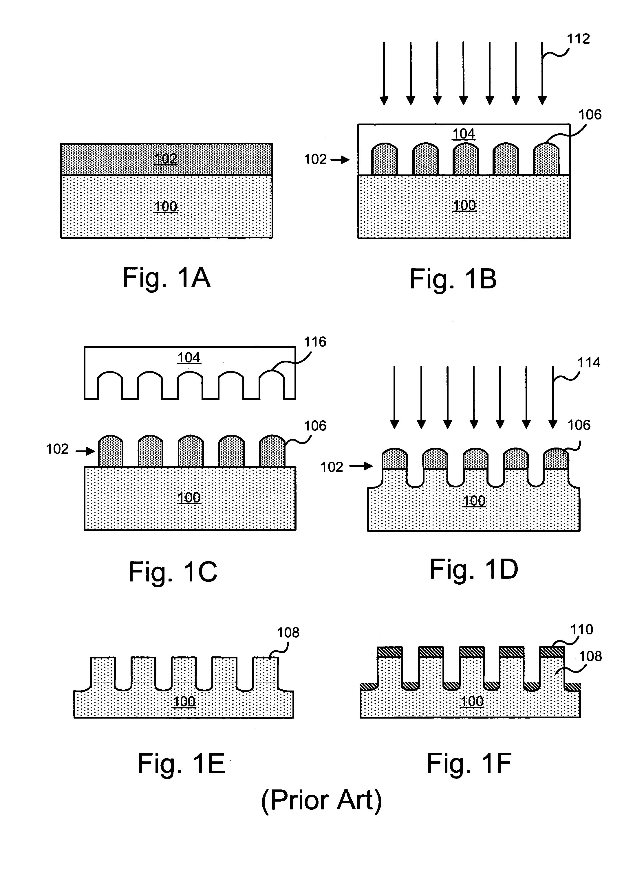
Directly lifting the stamper 104 requires a large force to achieve separation that may cause mechanical damage to the imprinted features.
Direct contact with the substrate 100 surface and / or the stamper 104 surface is generally undesirable because contact can also damage the miniscule features and impair any potential functions, such as data throughput, for example.
Furthermore, using a chisel or wedge to propagate a Mode 1 crack from the outside diameter of a disk or the like may reduce the amount of force required for separation, but can also introduce unbalanced forces causing non-uniform separation.
To initiate a uniform separation, multiple wedges functioning simultaneously, mechanical tilting, or other mechanical feats that are difficult to achieve may be required.

Method used


Image

  • Method and apparatus for separating a stamper from a patterned substrate
  • Method and apparatus for separating a stamper from a patterned substrate
  • Method and apparatus for separating a stamper from a patterned substrate

Examples


Embodiment Construction

[0032] Reference throughout this specification to “one embodiment,”“an embodiment,” or similar language means that a particular feature, structure, or characteristic described in connection with the embodiment is included in at least one embodiment of the present invention. Thus, appearances of the phrases “in one embodiment,”“in an embodiment,” and similar language throughout this specification may, but do not necessarily, all refer to the same embodiment.

[0033] Furthermore, the described features, structures, or characteristics of the invention may be combined in any suitable manner in one or more embodiments. In the following description, numerous specific details are disclosed to provide a thorough understanding of embodiments of the present invention. One skilled in the relevant art will recognize, however, that the invention may be practiced without one or more of the specific details, or with other methods, components, materials, and so forth. In other instances, well-known ...


PUM

PropertyMeasurementUnit
Forceaaaaaaaaaa
Diameteraaaaaaaaaa
Adhesion strengthaaaaaaaaaa

Abstract

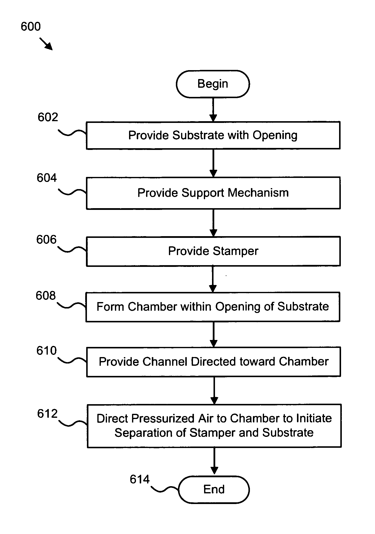
A method and apparatus are disclosed for separating a stamper from a patterned substrate. The method includes providing a substrate having a top and a bottom with an opening therein, providing a support mechanism configured to retain the substrate, providing a stamper having a formed pattern and configured to come in contact with the top of the substrate, wherein a chamber is formed within the opening of the substrate when the stamper is in contact with the substrate, providing a channel directed toward the chamber to introduce pressurized air into the chamber, and directing pressured air through the channel to the chamber to initiate separation of the stamper from the substrate. In certain embodiments, the pressurized air may be directed toward an opening in the substrate, such as a central ID hole in a disk. The disk may be incorporated within a storage device as pattered magnetic media.

Description

BACKGROUND OF THE INVENTION [0001] 1. Field of the Invention [0002] This invention relates to a method and apparatus for patterning a substrate and more particularly relates to a method and apparatus for separating a stamper from a patterned substrate. [0003] 2. Description of the Related Art [0004] Nanoimprint technology has developed rapidly in the past decade and offers promising advancements with regards to the replication of nanometer-scaled structures. The technological improvements have been a boon to several growing industries including integrated circuits (IC), micro electro mechanical systems (MEMS), and magnetic storage mediums. Replicating minute structures, however, introduces several problems that must be surmounted in order to refine the imprinting process. Forces such as friction and adhesion, for example, must be overcome in order to achieve optimal results. In addition, inexpensive mechanisms and simplistic methods are needed to advance the imprinting process and t...

Claims


Application Information

Patent Timeline
IPC IPC(8): B29D11/00
CPCB82Y10/00B82Y40/00G03F7/0002G11B5/865G11B5/82G11B5/855G11B5/743Y10S977/887
Inventor BEST, MARGARET EVANSWU, TSAI-WEI
Owner WESTERN DIGITAL TECH INC
Why Eureka
Try Eureka