
Electro-Optical Element Including Metallic Films and Methods For Applying The Same

Active Publication Date: 2007-08-30
GENTEX CORP
View PDF15 Cites 96 Cited by
  • Summary
  • Abstract
  • Description
  • Claims
  • Application Information

AI Technical Summary

Problems solved by technology

Although this concept was described as early as 1966, no group had commercial success because of the exacting criteria demanded from a workable auto-dimming mirror incorporating a third surface reflector.
Although a third surface reflector is discussed therein, the materials listed as being useful as a third surface reflector suffer from the deficiencies of not having sufficient reflectivity for use as an inside mirror, and / or not being stable when in contact with a solution-phase electrochromic medium containing at least one solution-phase electrochromic material.
However, the conductivity of such systems is limited by the sheer number of particle to particle connections that must be made in order to conduct current.
Each particle to particle connection adds electrical resistance, thereby limiting the usefulness of metal particle loaded resins.
Currently, it is not possible to obtain mirror-quality specular light reflection from such films since the random orientation of the relatively large metal particles promotes diffuse reflection.
However, the equipment for vacuum-based processes is expensive to purchase, operate, and maintain.
It is further difficult to deposit pattern films using vacuum-based processes.
Such masks can be expensive to machine and difficult to maintain.
Aside from increasing the complexity of the overall manufacturing process, the aforementioned sputtering or evaporation processes are also not efficient in the use of metal or metal precursors.
Specifically, a significant amount of metal is deposited on the masking and surrounding structure rather than on the desired device during the vacuum processing, the reclamation of the which is costly and time consuming.

Method used


Image

  • Electro-Optical Element Including Metallic Films and Methods For Applying The Same
  • Electro-Optical Element Including Metallic Films and Methods For Applying The Same
  • Electro-Optical Element Including Metallic Films and Methods For Applying The Same

Examples


example 1

[0061]Inkjet Silver Conductor AG-IJ-G-100-S1 ink from Cabot Printable Electronics and Displays (Albuquerque, N. Mex.) was applied to flat, 1.6 mm thick, soda lime glass using a JetDrive III driver and MJ-AB-01 40 μm inkjet head both obtained from MicroFab Technologies (Plano, Tex.). Printing parameter settings were typical for inkjet printing. After the conductive ink was printed, separate samples were cured in a convection oven or kiln at temperatures of 200, 300, 400, and 500° C. for 20 minutes. The thickness of the cured films was measured using a profilometer (Dektek) and bulk resistivity was calculated.

Bulk ResistivityCureCureThickness (μm)(μΩ· cm)Temperature (° C.)Time (min)(avg. of 3)(avg. of 3)200200.8710.63300201.064.24400200.862.90500201.003.11

[0062]The adhesion between the film and the substrate was evaluated by a tape peel test. After curing, adhesive tape was applied to the film and removed with a peeling action. A rating of 1 indicates the film was removed by the tape....

example 2

[0063]Silverjet DGH 50LT-25CIA ink from Advanced Nano Products (Seoul, Korea) was applied to flat, 1.6 mm thick, soda lime glass using similar apparatus and printing parameter settings as Example 1. After the conductive ink was printed, separate samples were cured in a convection oven or kiln at temperatures of 250, 350, 450, and 560° C. for 20 minutes. The thickness of the cured films was measured using a profilometer (Dektek) and bulk resistivity was calculated.

Bulk ResistivityCureCureThickness (μm)(μΩ· cm)Temperature (° C.)Time (min)(avg. of 3)(avg. of 3)250203.4511.64350203.0610.69450202.509.65560201.483.34

[0064]The adhesion between the film and the substrate was evaluated by a tape peel test as described in Example 1. A rating of 1 indicates the film was removed by the tape. A rating of 5 indicates the film was not affected by the tape removal. Intermediate numbers are assigned by how much of the film is removed by the tape removal.

Cure Temperature (° C.)Cure Time (min)Adhesion...

example 3

[0065]Silverjet DGH 50HT-50CIA ink from Advanced Nano Products (Seoul, Korea) was applied to flat, 1.6 mm thick, soda lime glass using similar apparatus and printing parameter settings as Example 1. After the conductive ink was printed, separate samples were cured in a convection oven or kiln at temperatures of 250, 350, 450, and 560° C. for 20 minutes. The thickness of the cured films was measured using a profilometer (Dektek) and bulk resistivity was calculated.

Bulk ResistivityCureCureThickness (μm)(μΩ· cm)Temperature (° C.)Time (min)(avg. of 3)(avg. of 3)250205.3818.17350205.2917.23450205.3117.89560203.287.39

[0066]The adhesion between the film and the substrate was evaluated by a tape peel test as described in Example 1. A rating of 1 indicates the film was removed by the tape. A rating of 5 indicates the film was not affected by the tape removal. Intermediate numbers are assigned by how much of the film is removed by the tape removal.

Cure Temperature (° C.)Cure Time (min)Adhesio...


PUM


Abstract

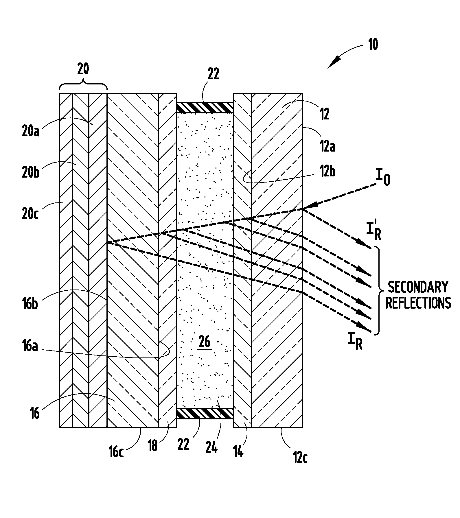
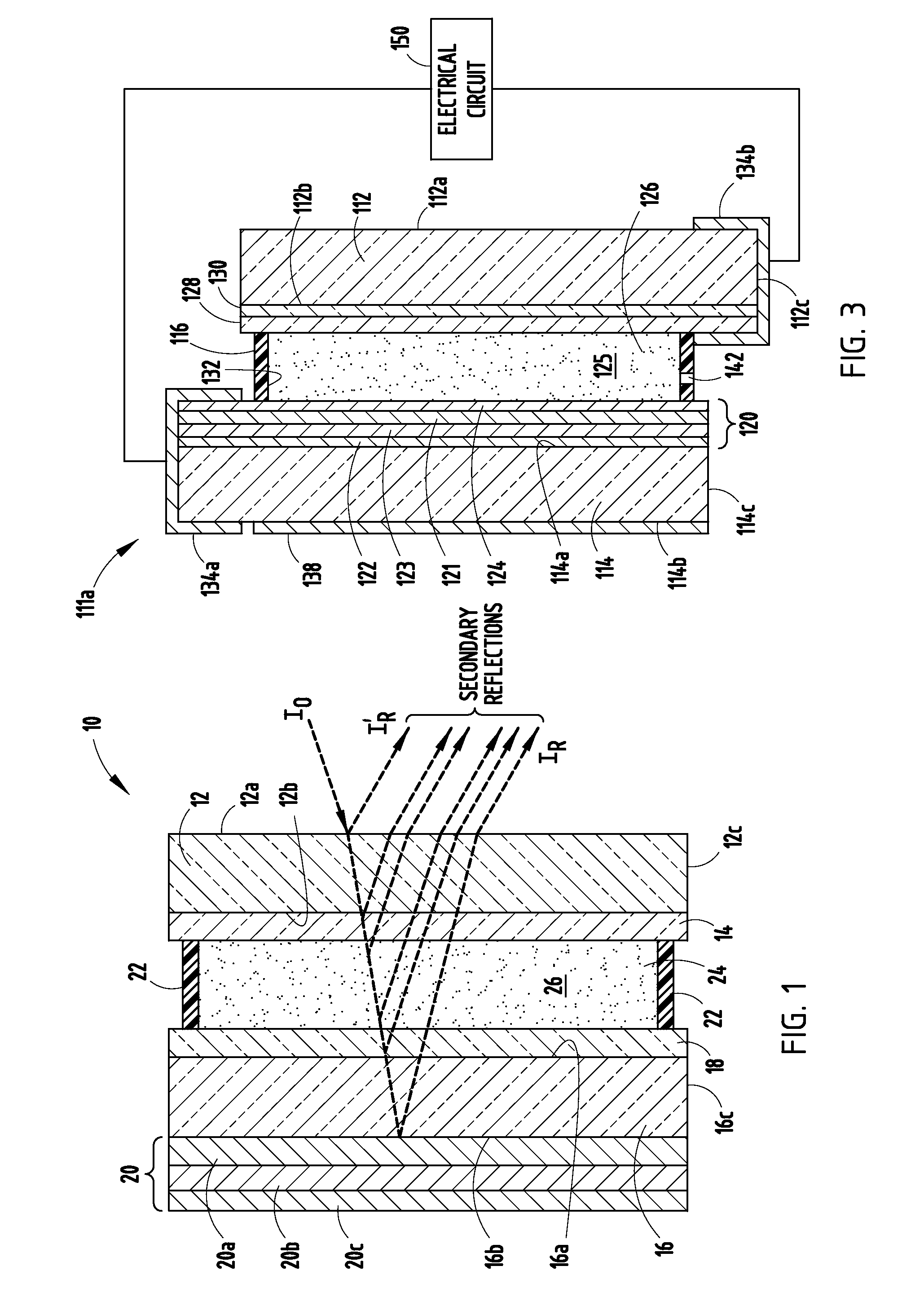
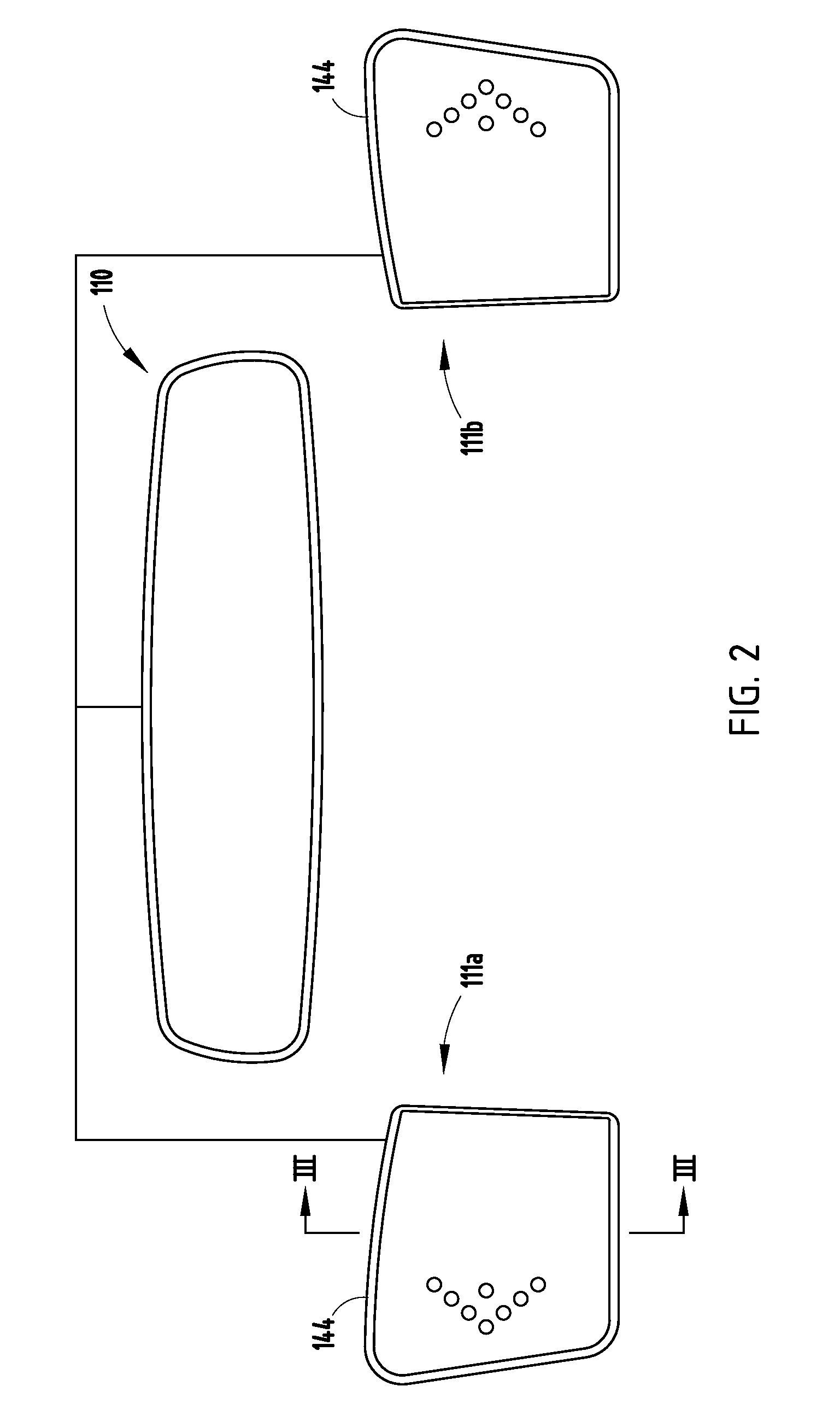
A method for manufacturing an electrochromic element comprises providing a first substrate having first and second surfaces and a first edge surface, providing a second substrate having third and fourth surfaces and a second edge surface, the third surfaces facing the second surface, providing an electrochromic medium located between the first and second substrates, the medium having a light transmittance that is variable upon application of electric field thereto, applying a conductive layer on a portion of at least one of the surfaces, wherein applying the layer is accomplished at substantially atmospheric pressure, and applying at least one of metallic particles, an organometallic, a metallo-organic, and combinations thereof, wherein the conductive layer has a bulk resistivity of greater than or equal to 150 μΩ·cm. The conductive layer may be applied via ink jetting, ultrasonic spraying, auger or jet pumping.

Description

CROSS REFERENCE TO RELATED APPLICATIONS[0001]This application claims the benefit of U.S. Provisional Application No. 60 / 779,369, filed Mar. 3, 2006, entitled IMPROVED COATINGS AND REARVIEW ELEMENTS INCORPORATING THE COATINGS, and U.S. Provisional Application No. 60 / 810,921, filed Jun. 5, 2006, entitled ELECTROCHROMIC REARVIEW MIRROR ASSEMBLY INCORPORATING A DISPLAY / SIGNAL LIGHT, both of which are hereby incorporated herein by reference in their entirety, and is a continuation-in-part of U.S. patent application Ser. No. 10 / 863,638, filed Jun. 8, 2004, entitled REARVIEW MIRROR ELEMENT HAVING A CIRCUIT MOUNTED To THE REAR SURFACE OF THE ELEMENT.BACKGROUND OF THE INVENTION[0002]This invention relates to electrochromic elements as utilized within rearview mirror assemblies for motor vehicles, as well as within window assemblies, and more particularly, to improved electrochromic elements for use within such assemblies. More particularly, the present invention relates to electrochromic ele...

Claims


Application Information

Patent Timeline
IPC IPC(8): G02F1/15
CPCB60R1/088G02F2202/36G02F1/155B82Y20/00Y10S359/90
Inventor DOZEMAN, GARY J.LUTEN, HENRY A.NEUMAN, GEORGE A.TONAR, WILLIAM L.GUARR, THOMAS F.KLOEPPNER, LEROY J.EATON, DAVID L.
Owner GENTEX CORP
Learn More