Method for controlling the idle speed of an internal combustion engine, and an internal combustion engine
- Summary
- Abstract
- Description
- Claims
- Application Information
AI Technical Summary
Benefits of technology
Problems solved by technology
Method used
Image
Examples
Embodiment Construction
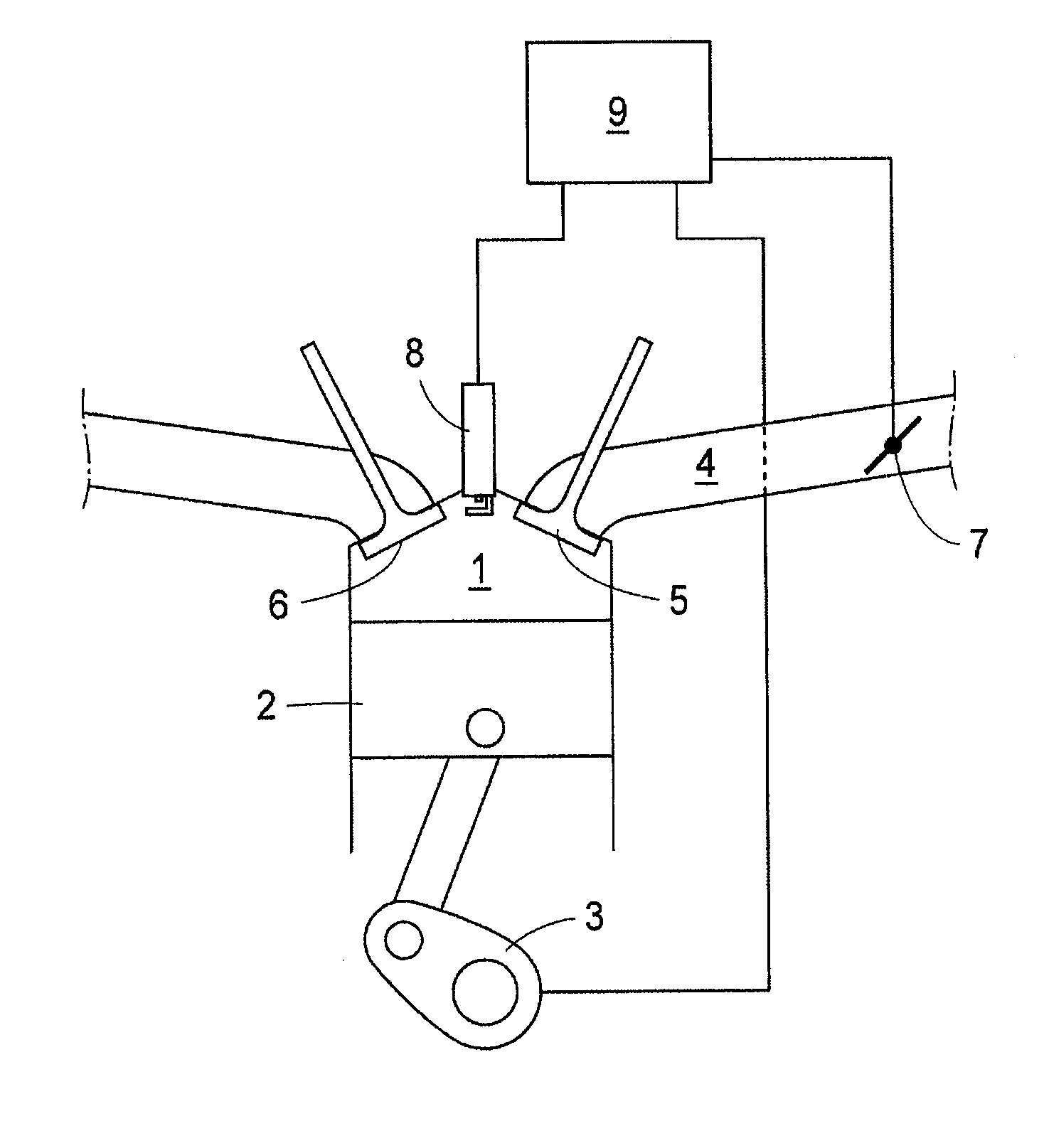
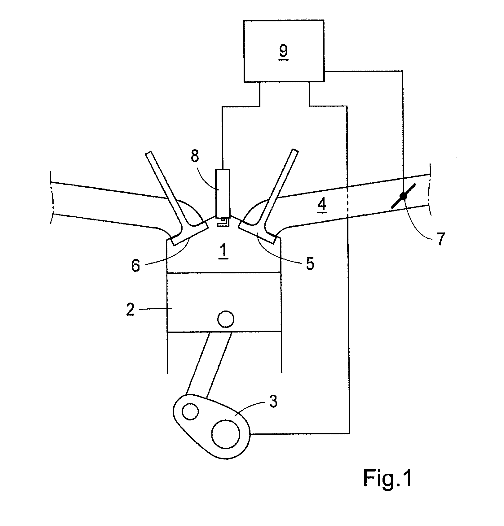
[0014]FIG. 1 shows schematically parts of an internal combustion engine, comprising a cylinder 1, a piston 2, a crankshaft 3, an inlet manifold 4, an inlet and an outlet valve 5, 6, a throttle valve 7 in the inlet manifold, and a spark plug 8. A control unit in the form of an engine control unit (ECU) 9 is provided. The ECU 9 has computational and data storage capabilities, and can be provided as one physical unit, or alternatively as a plurality of logically interconnected units. The ECU 9 is arranged to receive signals corresponding to the engine speed, for example by means of a toothed wheel on the crankshaft 3. The ECU 9 is also arranged to send control signals so as to control the position of the throttle valve 7. Further, the ECU is arranged to send control signals so as to control the timing of spark ignitions of the spark plug 8.
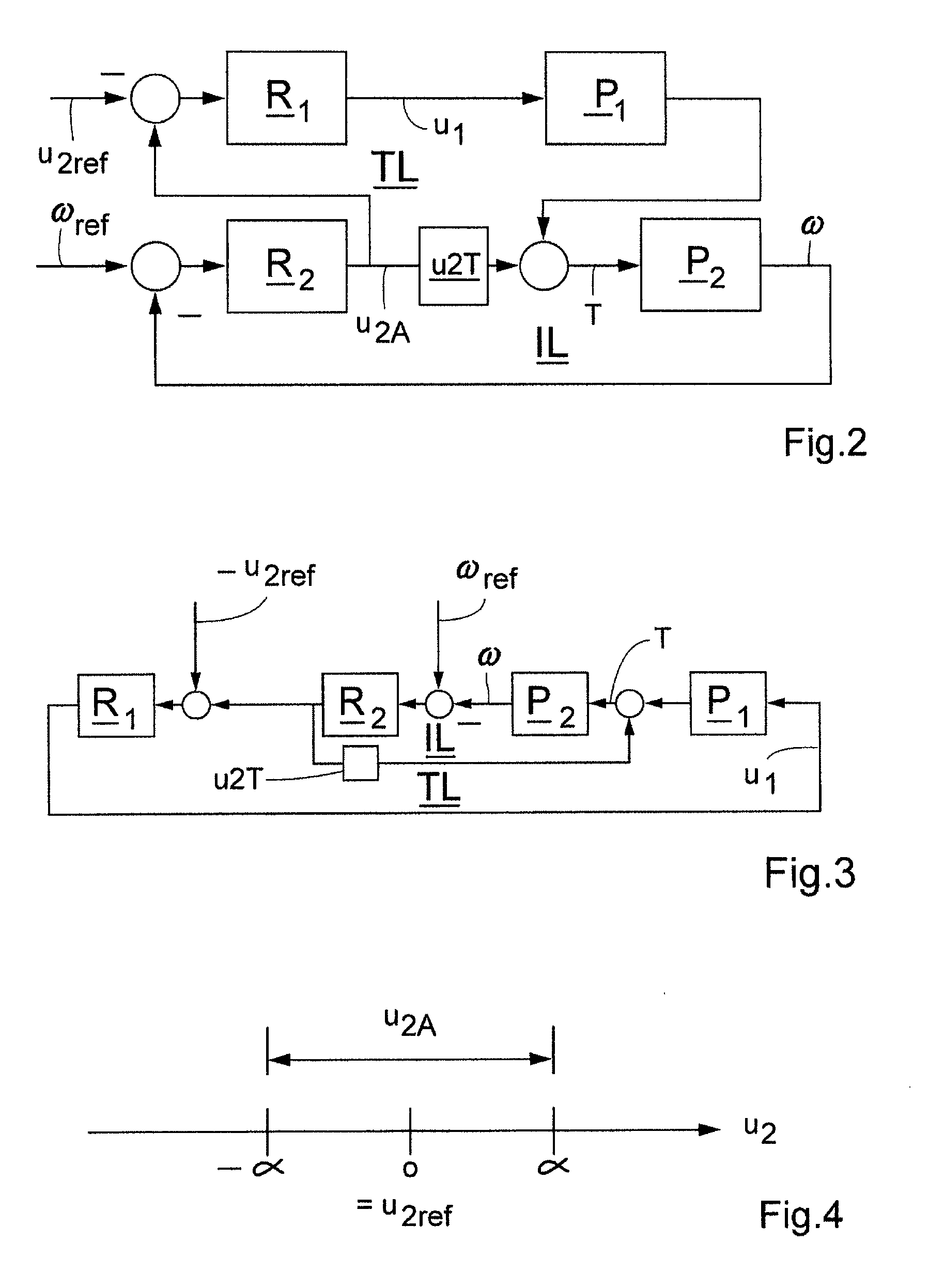
[0015]FIG. 2 shows a block diagram depicting the method of the ECU 9 to control the idle speed of the engine. As explained in greater detail below, ...
PUM
 Abstract
Description
Claims
Application Information
 - R&D
- Intellectual Property
- Life Sciences
- Materials
- Tech Scout
- Unparalleled Data Quality
- Higher Quality Content
- 60% Fewer Hallucinations
Browse by: Latest US Patents, China's latest patents, Technical Efficacy Thesaurus, Application Domain, Technology Topic, Popular Technical Reports.
© 2025 PatSnap. All rights reserved.Legal|Privacy policy|Modern Slavery Act Transparency Statement|Sitemap|About US| Contact US: help@patsnap.com


