
Flooring system and method of installing same

a technology of floor panels, applied in the field of floor coverings, can solve the problems of gaps between floor strips or planks, gaps can become filled with dirt and grime, and expand or shrink,

Inactive Publication Date: 2007-08-23
PLANTE REJEAN
View PDF2 Cites 15 Cited by
  • Summary
  • Abstract
  • Description
  • Claims
  • Application Information

AI Technical Summary

Benefits of technology

[0014] It is an object of this invention to provide a flooring system which can compensate for the expansion and contraction of wood used for flooring purposes.
[0015] It is another object of this invention to provide a flooring system that does not require a traditional expansion joint cover.
[0016] It is another object of this invention to provide a flooring system that reduces consumption of wood by having a groove and groove profile.
[0020] By being able to work with for the expansion / contraction, it is possible to create planks that are much wider than usually done in the industry which makes it possible for an installer to install a floor much faster since fewer pieces are needed to cover a given surface.
[0023] In accordance with a further general aspect of the present invention, there is provided a flooring system comprising first and second flooring members adapted to be laid down side-by-side in a coplanar relationship, and a floating interlocking joint between said first and second flooring members, said floating interlocking joint comprising a compressible / stretchable filler provided in a gap between opposed facing sides of said first and second flooring members, said filler being adhesively engaged with said opposed facing sides, and a locking key provided on a first one of said opposed facing sides and engageable with a complementary locking groove provided in a second one of said opposed facing sides, said locking key having a limited freedom of movement within said locking groove in a direction perpendicular to said opposed facing sides to accommodate expansion and contraction movements of said first and second flooring members.
[0024] In accordance with a further general aspect of the present invention, there is provided a floor plank adapted to be laid in a coplanar side-by-side relationship with similar floor planks to form a floor surface, said floor plank comprising an internal expansion / contraction accommodation means to provide for local absorption of floor expansion and contraction movements and prevent chain transmission of stresses from one plank to another, said internal expansion / contraction accommodation means comprising at least one top groove defined in an exposed top surface of said floor plank.

Problems solved by technology

Due to wood's hygroscopic nature, variations in relative humidity make it expand or shrink.
Shrinkage will cause gaps between the floor strips or planks.
Over time, these gaps can become filled with dirt and grime which can host germs or even microorganisms which can attack wood fibers since the sides of floor strips or planks are not varnished or sealed in any way like the top finished face is.
Introducing moisture into the side of the strips or planks will cause a localized swelling of the sides of the strips or planks.
The wider a plank of solid wood is, the higher the risk that it will warp along its width.
This has the inconvenience of requiring an expansion joint which needs to be covered.
This expansion joint cover is generally very apparent and not very esthetically pleasing.
Moreover, since it is installed with an overlap covering the top of the floor it cannot be level with the floor and creates an undesirable “threshold” appearance.

Method used


Image

  • Flooring system and method of installing same
  • Flooring system and method of installing same
  • Flooring system and method of installing same

Examples


Embodiment Construction

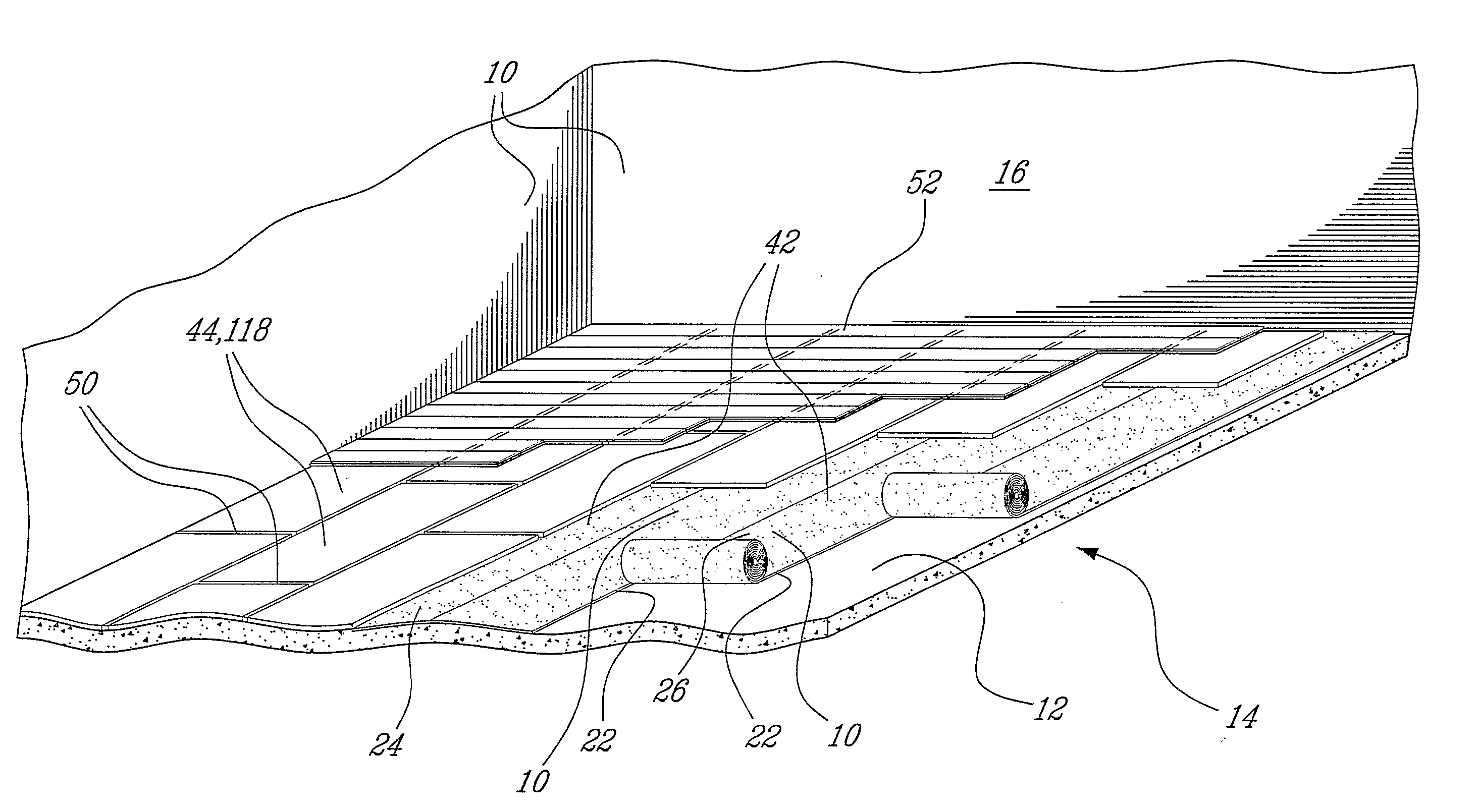
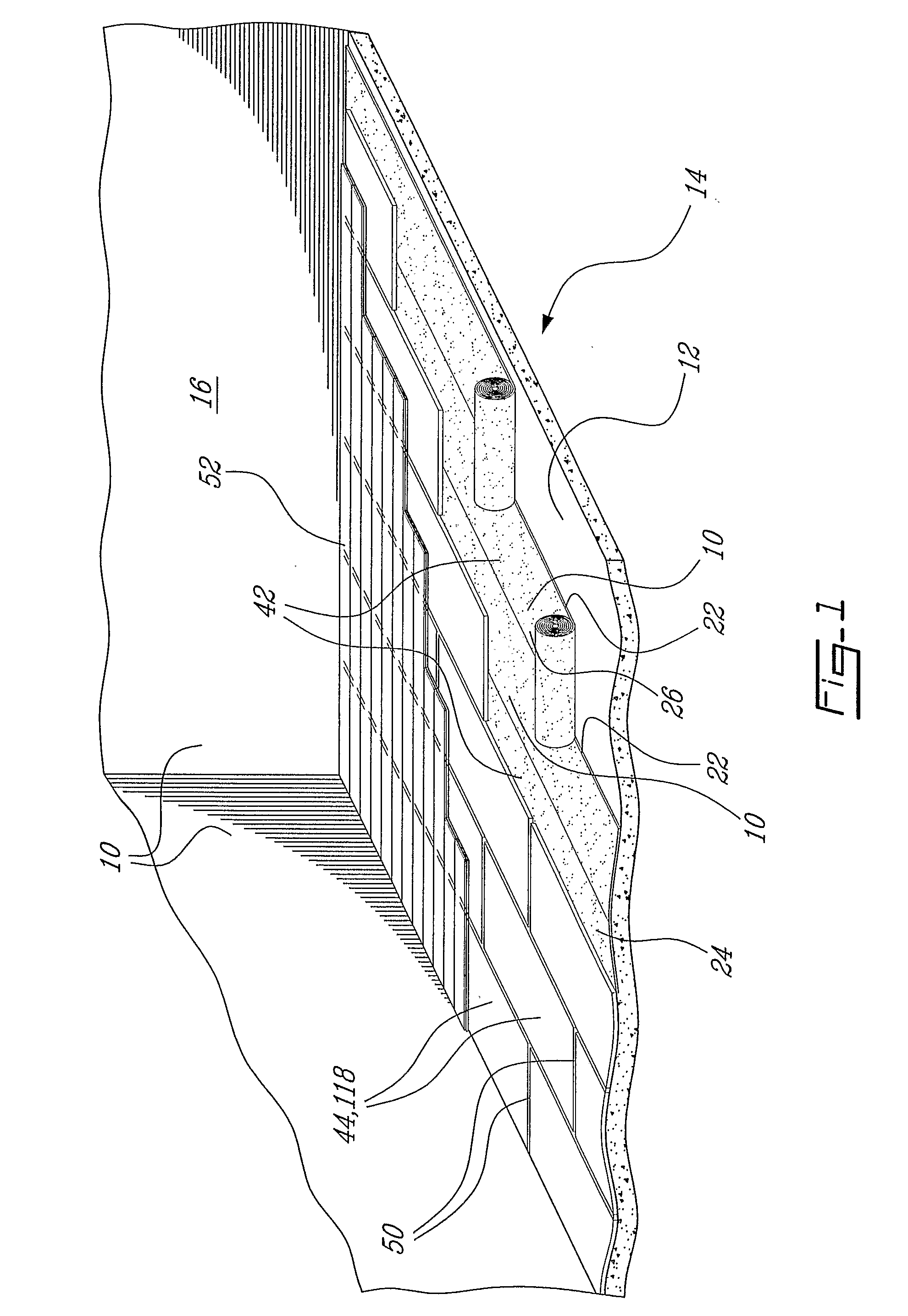
[0027]FIG. 1 is a perspective view of a floor assembly;

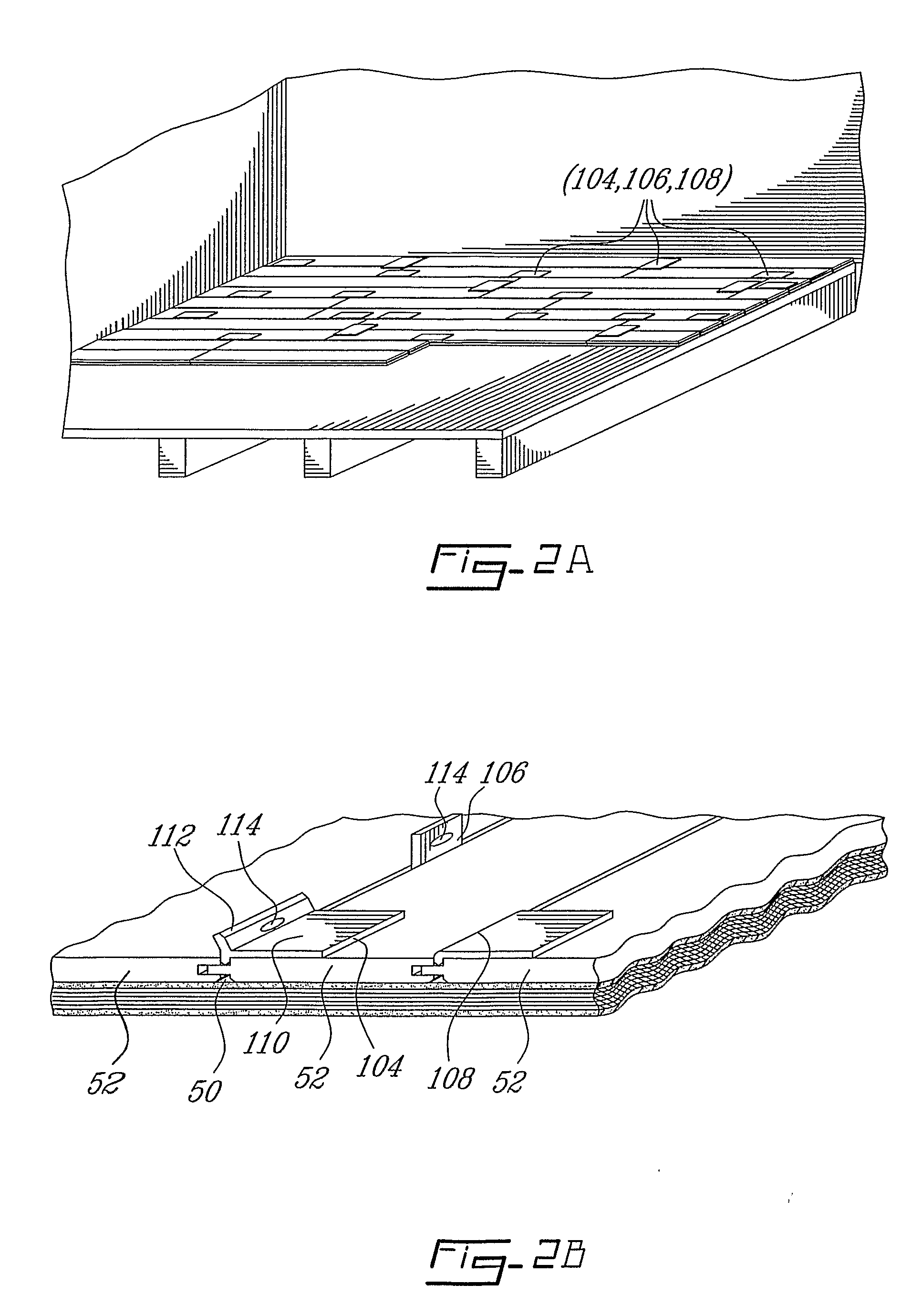
[0028]FIGS. 2ab are perspective views showing the laying of a floor using inter-plank spacing with spacers;

[0029]FIG. 3a is a perspective view of groove and groove profile, hardwood, with two types of splines;

[0030]FIG. 3b is a perspective view of groove and groove profile, multi-ply, with two types of splines;

[0031]FIG. 3c is a perspective view of groove and groove profile, MDF / HDF with two types of splines;

[0032]FIG. 3d is a perspective view of a floating key lock joint and filler;

[0033]FIG. 3e is a perspective view of a floating key lock joint and filler when compressed as a result of plank expansion;

[0034]FIG. 3f is a perspective view of a key lock joint of the prior art;

[0035]FIGS. 4ab are perspective view of prior art regarding pushing out of nailing;

[0036]FIGS. 5ab are perspective view of prior art hardwood floor;

[0037]FIGS. 6ab are perspective view of a multi-groove system;

[0038]FIGS. 7, 8ab illustrate variati...


PUM


Abstract

A flooring system is provided with a combination of features which work with the expansion / contraction naturally occurring when wood is subjected to moisture variations. Part of the process is taken within the plank (52), which is the internal or intra-plank compensation system (82) and another part is taken by interacting between the planks (52) which is the inter-plank compensation system (50, 60).

Description

BACKGROUND OF THE INVENTION [0001] 1. Field of the Invention [0002] This invention relates generally to flooring but more particularly to a floor having means for compensating for wood expansion and contraction. [0003] 2. Description of the Prior Art [0004] The prior art reveals many developments in wood floors or at least to floors that look like wood. Indeed, recent developments have proposed floor structures in which natural wood makes but a very small percentage of the content or none at all. A lot of substrates are made of wood based products mixed with various resins and polymers covered with a thin veneer of either natural wood or of melamine with a hard varnish finish. Because of problems related to the use of carpeting, mainly due to reported cases of allergies, wood floors or any such floor coverings made to look like wood have taken a greater share of the marketplace. Also, wood or wood looking finishes can be used on walls and even ceilings. [0005] Besides the combinatio...

Claims


Application Information

Patent Timeline
IPC IPC(8): E04B2/00E04C2/30E04F15/00E04F15/02E04F15/04E04F15/18E04F21/00
CPCB32B21/00E04F2203/08E04F15/02005E04F15/02033E04F15/02166E04F15/04E04F15/18E04F21/0092E04F21/22E04F2201/0153E04F2201/03E04F2201/042E04F2201/05E04F2201/0523E04F2201/07E04F15/02E04F15/02016
Inventor PLANTE, REJEAN
Owner PLANTE REJEAN
Learn More