
Security appliances

a technology for security appliances and computers, applied in the field of computer security, can solve the problems of network administrators plagued by the issue of unauthorized users (hackers) and their exploits, and achieve the effects of long design, development and release cycles

Inactive Publication Date: 2007-08-16
NETCLARITY
View PDF43 Cites 163 Cited by
  • Summary
  • Abstract
  • Description
  • Claims
  • Application Information

AI Technical Summary

Benefits of technology

[0010] In one aspect, there is disclosed herein a security micro-appliance that provides dynamic, reconfigurable threat protection. The micro-appliance may be deployed as a standalone system, or as a component in a distributed security system

Problems solved by technology

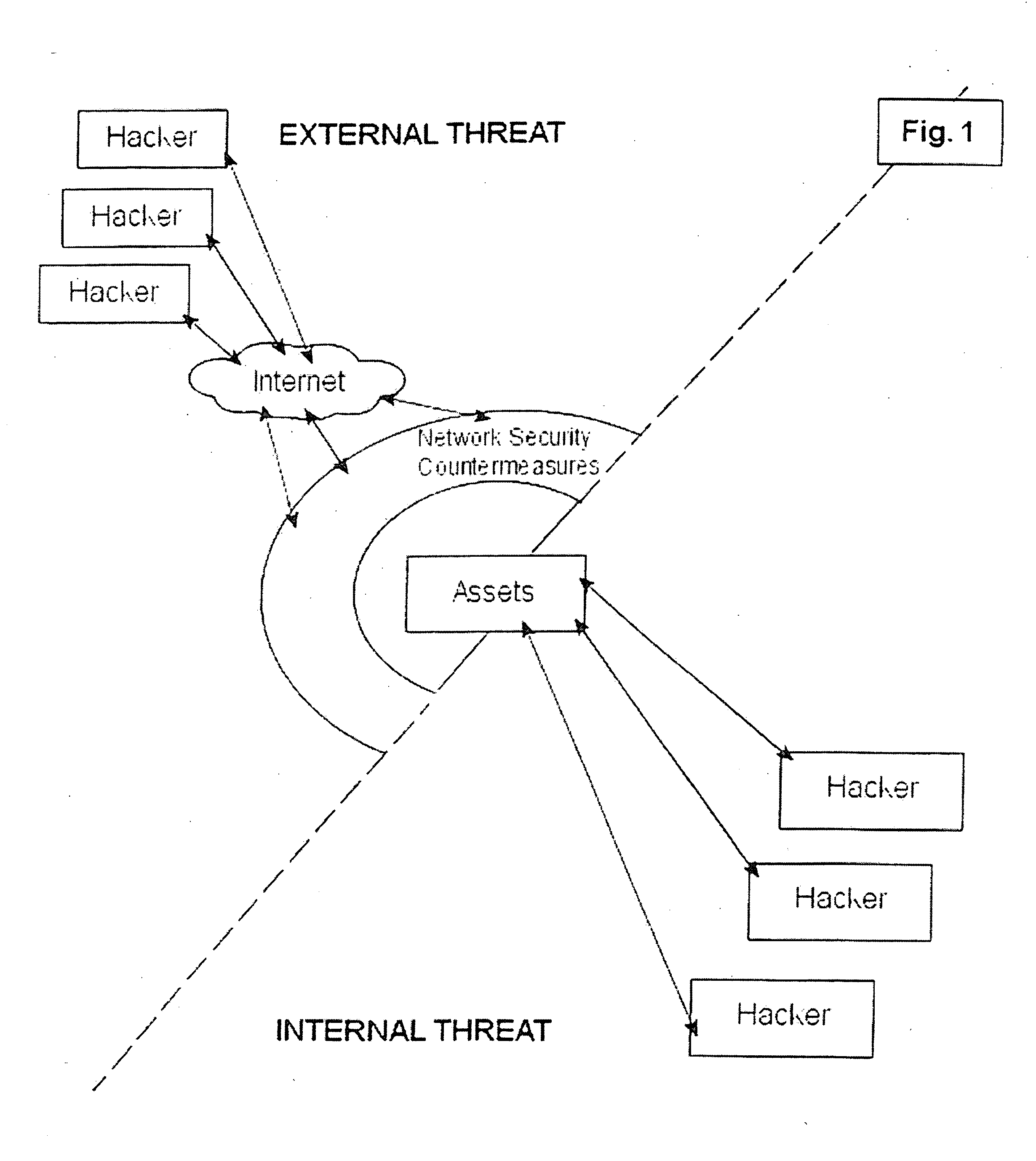
For years, network administrators have been plagued by the issue of unauthorized users (hackers) and their exploits (rootkits, viruses, worms, backdoors, spyware, etc.) who gain entry to the network by probing for weaknesses or misrepresenting their intentions when asking to use certain network services, such as asking for a network user to read an email message.
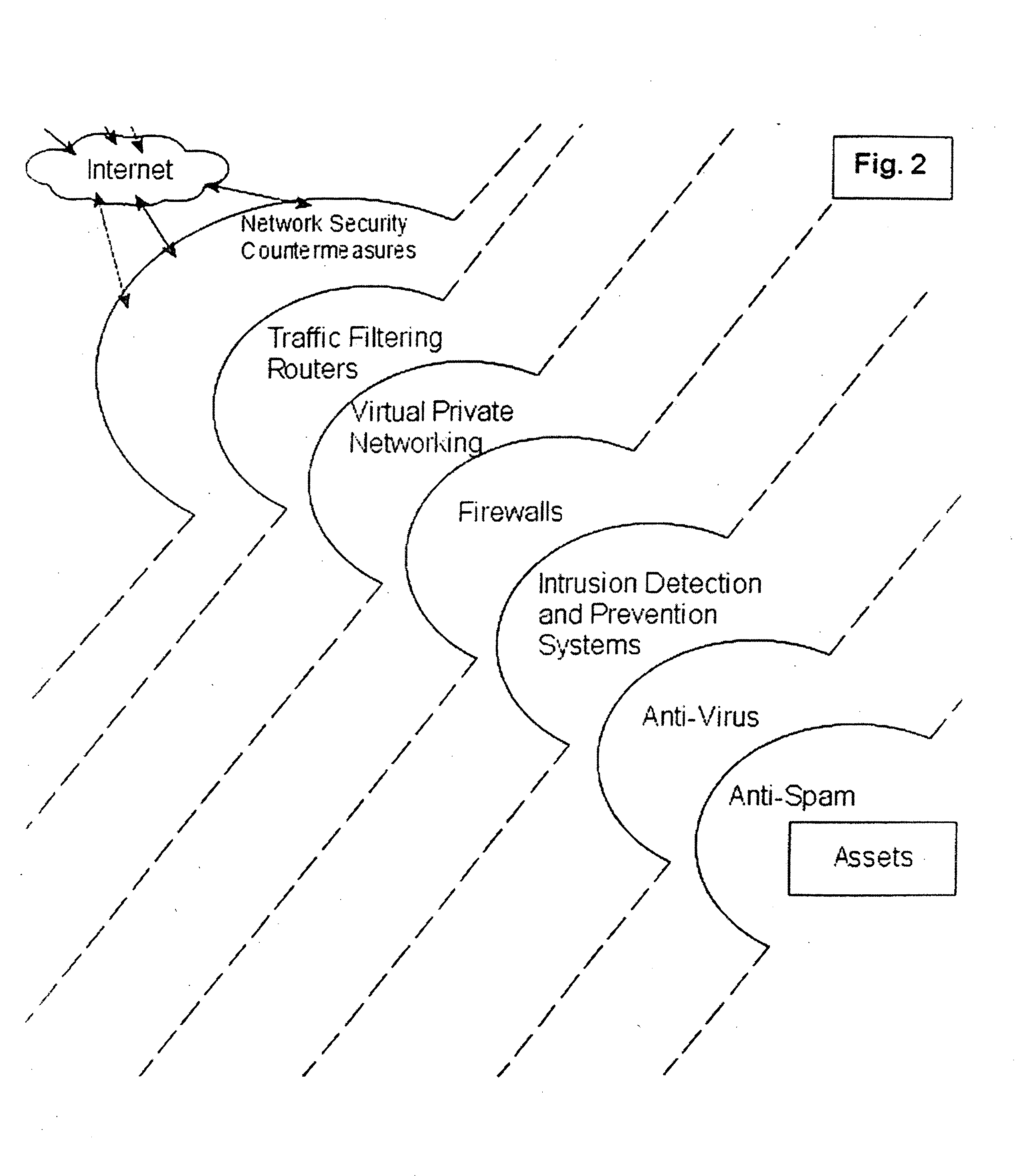
The main problem with conventional anti-hacker security system is that they are not designed to stop hackers, instead they are countermeasures that react to threats.
Thus, today's security systems still leave the network vulnerable to attack, although they are capable of addressing certain attacks once the attack is identified.
Another problem with conventional anti hacker security systems is that they are typically built as proprietary systems, resulting in long design, development and release cycles.
This of course can be problematic as hackers release new attacks quite frequently, and because of the Internet, many of today's attacks spread with breathtaking speed from one network to another.
Unfortunately, most of today's INFOSEC solutions are hard to upgrade and manage.
For example, many of today's INFOSEC appliances have been “hard wired” with a CPU, and thus over time may be unable to keep up with user demand.
In fact, many INFOSEC systems today are “hard wired” with one or more network adapter interface for a 10 megabits per second network and if the network performance requirements move to 100 megabits per second or a gigabit per second, these INFOSEC appliances become bottlenecks to network performance and therefore detract from user productivity.
Still another problem with conventional anti hacker security system are that each INFOSEC appliance has a completely different and unique administrative interface.
After deploying more than a few of these appliances, it becomes extremely difficult for System Administrators (SYSADMINs) to manage these systems.

Method used


Image

  • Security appliances
  • Security appliances
  • Security appliances

Examples


Embodiment Construction

)

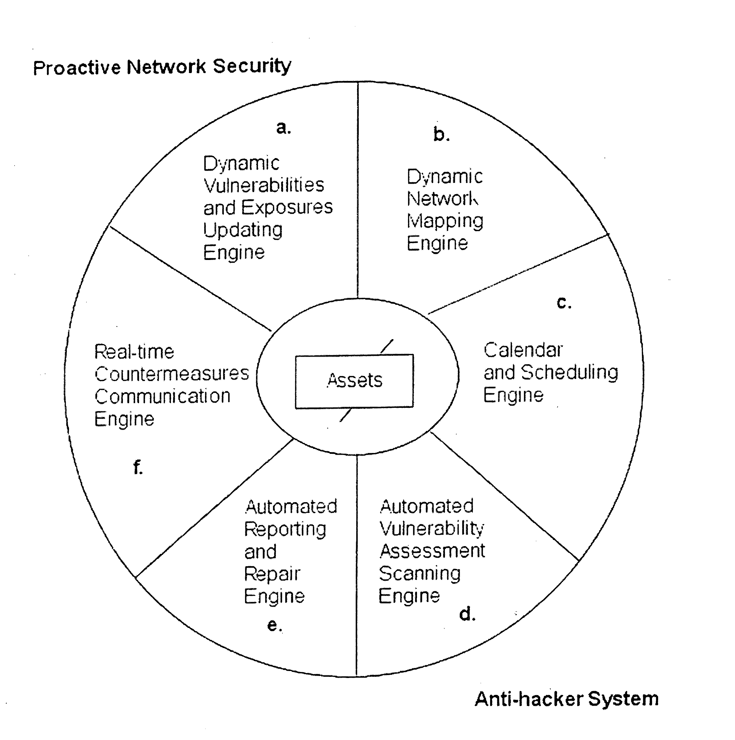
[0039] The system and methods described herein include, among other things, security systems that provide proactive automated defense against hackers by automatically finding, reporting, communicating with countermeasures about and removing the common vulnerabilities and exposures (CVEs) that they exploit. Accordingly, the systems described herein provide for proactive security by determining the components that exist on a network system and generating a list of network assets.

[0040] In one embodiment, the invention provides a security method that can be executed on a wired and / or wireless network. As part of the security method, in a first step the network is scanned and / or probed for any and all attached equipment and related assets, herein referred to as “network-based” assets. The method will dynamically detect and map changes to LAN and WAN connected equipment including searching for equipment which may be deemed as rogue and creating a network-based assets list, wherein the ...


PUM


Abstract

A security micro-appliance provides dynamic, reconfigurable threat protection. The micro-appliance may be deployed as a standalone system, or as a component in a distributed security system management from a central administrative location. In another aspect, a security appliance or micro-appliance employs RSS feeds and XML-based tests, alerts, and the like for monitoring and dynamic reconfiguration.

Description

RELATED APPLICATIONS [0001] This application claims the benefit of, and incorporates by reference herein in its entirety, U.S. Provisional Patent Application No. 60 / 646,336, filed Jan. 21, 2005. This application also claims the benefit of, and incorporates by reference herein in its entirety, a U.S. Provisional Patent Application having attorney docket no. NETC-0001-P61, filed on Jan. 16, 2006 and entitled “MICRO-APPLIANCE FOR SECURITY AND VULNERABILITY MANAGEMENT.” This application also claims the benefit of, and incorporates by reference herein in its entirety, a U.S. Provisional Patent Application having attorney docket no. RSS-SECURITY-122105, filed on Dec. 21, 2005 and entitled “PROACTIVE NETWORK SECURITY USING REALLY SIMPLE SYNDICATION (RSS)”. [0002] This application is a continuation-in-part of U.S. application Ser. No. 10 / 898900, filed on Jul. 26, 2004, the entire contents of which is incorporated herein by reference. That application also claims the benefit of U.S. Provisio...

Claims


Application Information

Patent Timeline
IPC IPC(8): G06F11/00
CPCH04L63/02H04L63/1433G06F21/577G06F21/552H04L63/20
Inventor MILIEFSKY, GARY S.
Owner NETCLARITY
Learn More