
Method and system for stopping elevators

a technology for elevators and elevators, applied in elevators, transportation and packaging, etc., can solve the problems of low reliability of elevators, and disturbing noise generation of relays, so as to avoid disturbing the switching noise of relays, facilitate maintenance, and reduce the effect of mounting effor

Inactive Publication Date: 2007-08-16
DANFOSS AS
View PDF6 Cites 62 Cited by
  • Summary
  • Abstract
  • Description
  • Claims
  • Application Information

AI Technical Summary

Benefits of technology

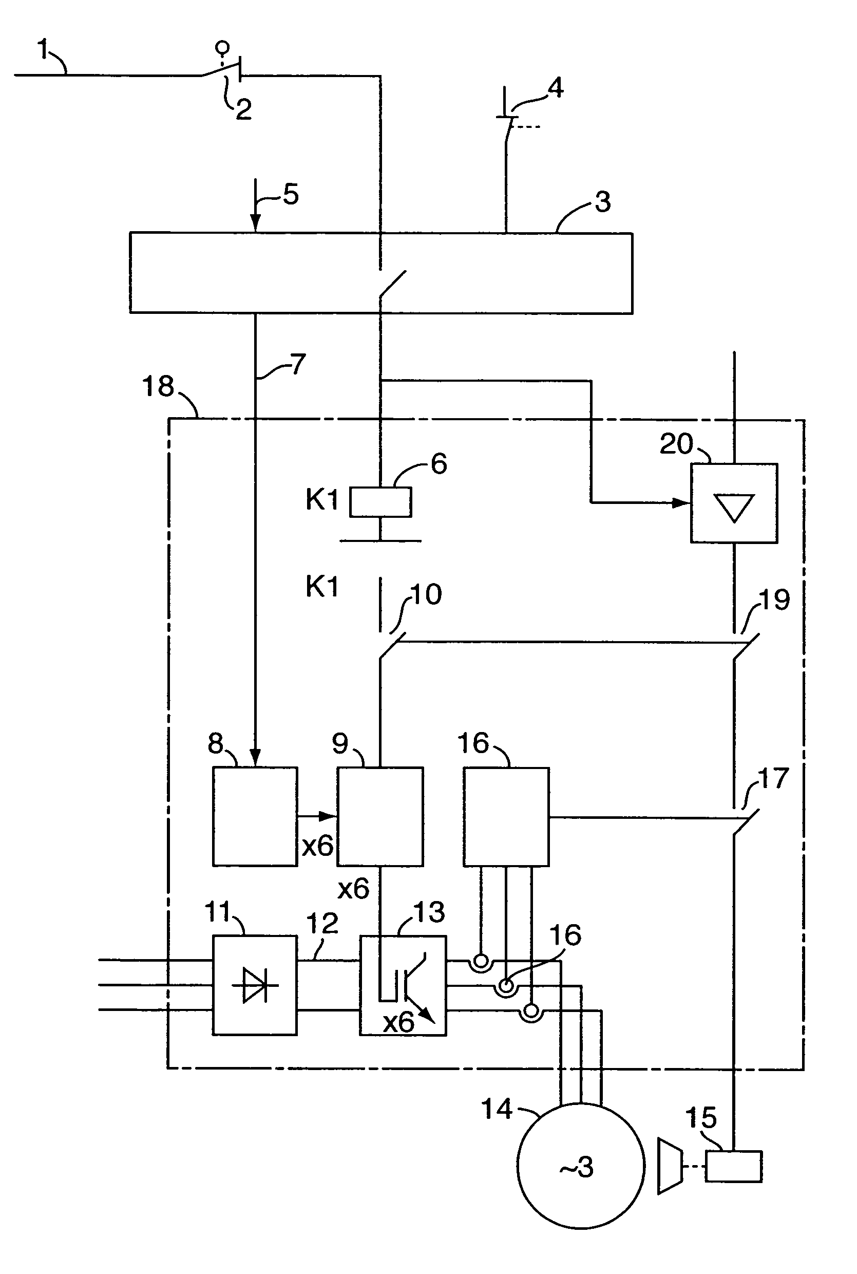
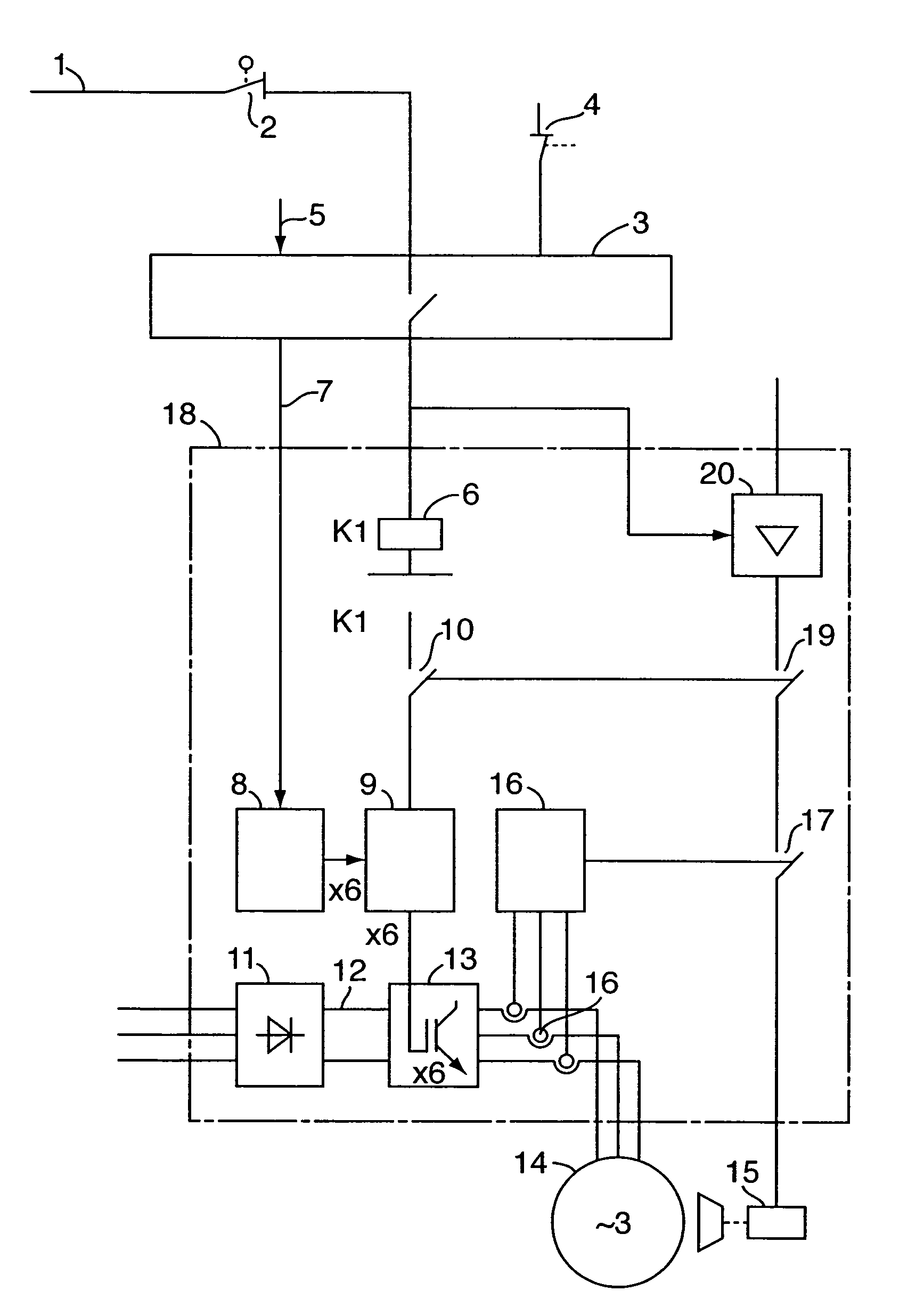
[0025] According to the invention, the stopping of the drive is achieved by means of a switching structure, which on the one hand safely disconnects the control signals creating the rotating field, that is, removing a driving torque of the motor, and on the other hand causes the activation of the brake belonging to the drive.
[0028] The safety system stopping the elevator works on the basis of a brake relay according to EN 954-1, category 4, integrated in the converter or on the basis of two monitored relays, which cause the actuation of the brake and at the same time act upon a safety switch according to EN 81-1. Thus, the safety switch interrupts the control impulses required for the modulation of the direct voltage. This prevents the generation of a rotating field creating motor torque.
[0030] Thus, the converter can be located dose to the drive or in the motor connection box of the drive. This enables integrated driving solutions for elevators with little mounting effort. The disturbing switching noises of the relays are avoided. The elevator control can be made substantially more compact, as the relays are no longer required and the converter can be located at the motor. The screening of the motor cables is not interrupted by the relays, or, in the case that the converter is located in the motor housing, is no longer required.

Problems solved by technology

Particularly with elevators without machine room, the space requirements and the noise generation of the relays to be used are disturbing.
Thus, it is difficult to locate the frequency converter directly at the motor.
The costs of the relays, their mounting and wiring increase the manufacturing costs.
From an EMV point of view, the switching of the frequency converter outlet and thus the interruption of the screening is bad.
It is also known that switching off the converter outlet at low motor frequencies generates higher contact erosion, which again causes a shorter life of the relays.

Method used


Image

  • Method and system for stopping elevators
  • Method and system for stopping elevators

Examples


Embodiment Construction

[0034] The safety circuit 1 of the elevator is usually made as series-connected safety systems 2, which act upon the brake relay 6 integrated in the frequency converter 18 via the elevator control 3.

[0035] The brake relay 6 is a relay according to EN 954-1, category 4, or can be realised by means of two monitored relays. By means of the contacts 19, the brake relay 6 controls the brake 15 of the motor 14 and acts upon the safety switch via contact 10. The safety switch preferably conforms to EN 81-1.

[0036] In order to reduce the contact wear, the power semiconductor 20 is connected in series with the contact 19 of the brake relay 6. Due to the faster switching behaviour of the power semiconductor 20, an erosion of the contact 19 is avoided.

[0037] The logic unit 8 of the frequency converter 18 provides the pulse pattern to the power semiconductors located in the inverter forming the torque. The safety switch 9 blocks the pulse pattern, when the contacts 10 of the brake relay are o...


PUM


Abstract

The invention relates to methods for stopping elevators especially when using at least one three-phase motor operated by a static frequency converter. According to the invention, a brake relay controls the brake of the motor such that releasing of the brake relay causes the motor to be decelerated while the brake relay is coupled to a protective circuit in such a way that the control pulses required for generating the driving motor field are safely blocked when the brake relay is released.

Description

CROSS REFERENCE TO RELATED APPLICATIONS [0001] This application is entitled to the benefit of and incorporates by reference essential subject matter disclosed in International Patent Application No. PCT / DE2005 / 000115 filed on Jan. 25, 2005 and German Patent Application No. 10 2004 006 049.5 filed Jan. 30, 2004.FIELD OF THE INVENTION [0002] The invention concerns a method and a system for stopping elevators using AC-motors driven by static frequency converters. BACKGROUND OF THE INVENTION [0003] The stopping of drives for elevators is technically relevant from a safety point of view. When considering the functional course of elevators, the stopping after activation of a safety device and the unintentional starting during loading or unloading, respectively, are particularly essential. [0004] In order to take these demands into account, the current supply to the motor is realised by means of two monitored relays or one monitored relay and one monitored control device, which interrupts ...

Claims


Application Information

Patent Timeline
Patent Type & Authority Applications(United States)
IPC IPC(8): B66B1/32B66B5/00B66B5/06
CPCB66B5/0031B66B1/308B66B5/00B66B5/0006B66B5/06
Inventor ABRAHAM, DETLEVMENNEN, HANS-JOSEF
Owner DANFOSS AS
Learn More