
Motor control apparatus, control method thereof, and program

A technology of motor control and current detection device, which is applied in the direction of motor generator control, AC motor control, control of electromechanical transmission devices, etc., can solve the waveform distortion of current command value, cannot prevent inverter switching noise, and adverse effects of motor control, etc. problem, to achieve the effect of preventing the occurrence of switching noise

Inactive Publication Date: 2019-12-10
TOYOTA JIDOSHA KK
View PDF9 Cites 0 Cited by
  • Summary
  • Abstract
  • Description
  • Claims
  • Application Information

AI Technical Summary

Problems solved by technology

However, the present inventors have found a problem that the correction of the current command value may cause the waveform distortion of the current command value to adversely affect the motor control
The present inventors have found another problem that, in the motor control device disclosed in Japanese Unexamined Patent Application Publication No. 2008-265645, when the duty cycle is changed, it may not be possible to prevent switching noise of the inverter from occurring, and thus motor control may be adversely affected

Method used


Image

  • Motor control apparatus, control method thereof, and program
  • Motor control apparatus, control method thereof, and program
  • Motor control apparatus, control method thereof, and program

Examples


no. 1 example

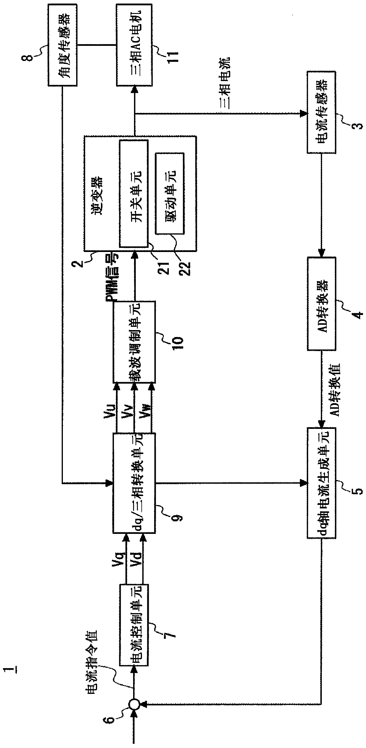
[0035] Hereinafter, embodiments of the present disclosure will be described with reference to the accompanying drawings. figure 1 is a block diagram showing a schematic system configuration of the motor control device according to the first embodiment of the present disclosure. The motor control device 1 according to the first embodiment controls a three-phase AC motor 11 . The three-phase AC motor 11 includes, for example, a rotor and a stator, and is composed of U-phase, V-phase, and W-phase.

[0036] The motor control device 1 according to the first embodiment includes an inverter 2, a current sensor 3, an AD converter 4, a dq-axis current generation unit 5, a calculation unit 6, a current control unit 7, an angle sensor 8, dq / three-phase conversion unit 9, and carrier modulation unit 10.

[0037] Note that the main hardware configuration of the motor control device 1 includes a microcomputer composed of, for example, a CPU (Central Processing Unit) that executes computat...

no. 2 example

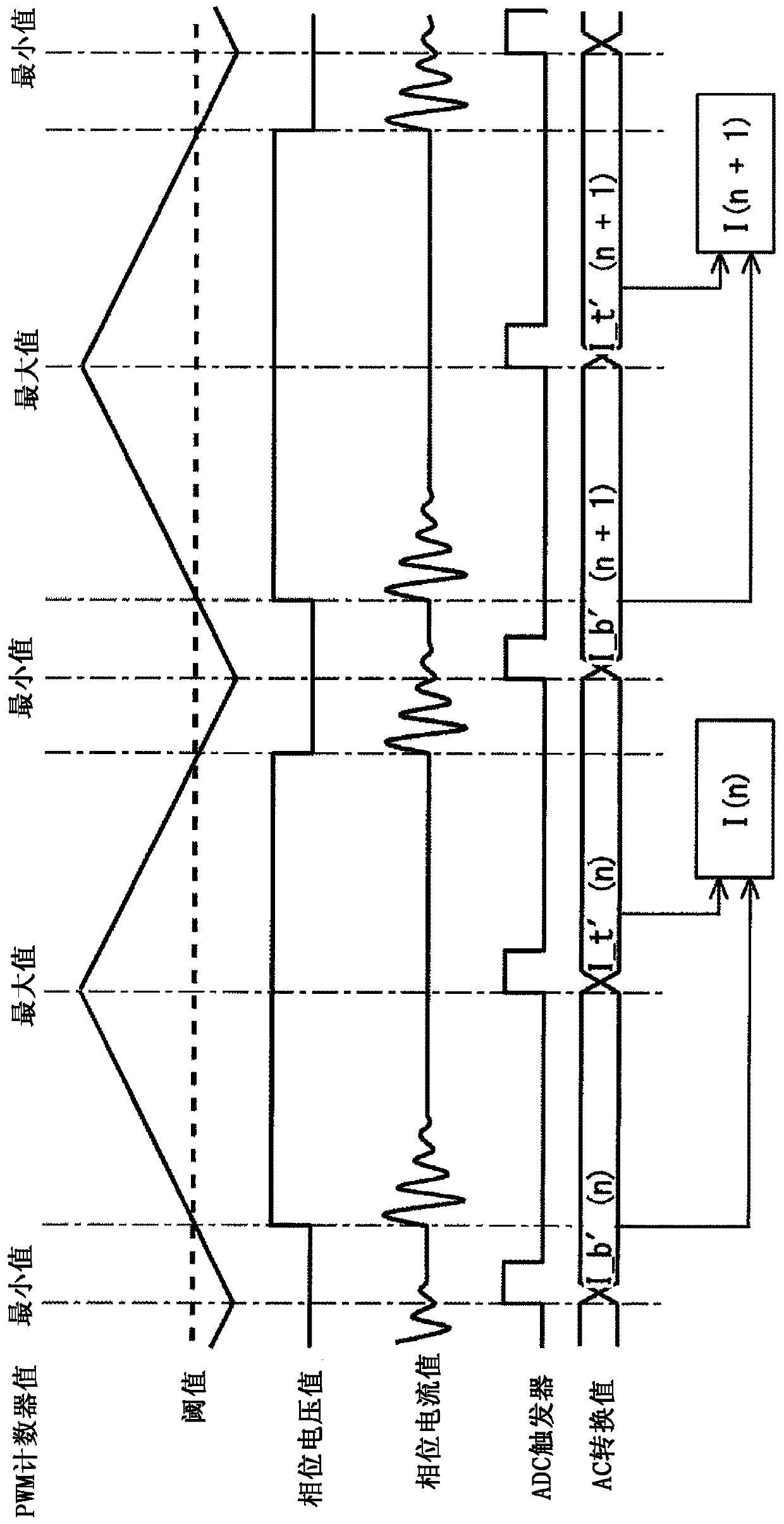
[0081] In the second embodiment of the present disclosure, the AD converter 4 can acquire a plurality of phase current values ​​from the current sensor 3 at the timing when the rectangular width of the rectangular wave of the phase voltage value corresponding to the PWM counter value is long I_b and I_t, the timing is also the timing when the PWM counter value becomes the minimum or maximum value (or the timing when the PWM counter value becomes 1 / 4 or 3 / 4 of the minimum or maximum value), and then The acquired phase current values ​​I_b and I_t are converted into AD converted values ​​I_b′ and I_t′, respectively. The AD converter 4 calculates the average values ​​I_b'ave and I_t'ave of a plurality of converted AD converted values, and outputs the calculated average values ​​I_b'ave and I_t'ave of the AD converted values ​​to the dq-axis current generation unit 5 .

[0082] When the AD converter 4 is fast enough for the period of the PWM signal, it is possible to acquire a pl...


PUM


Abstract

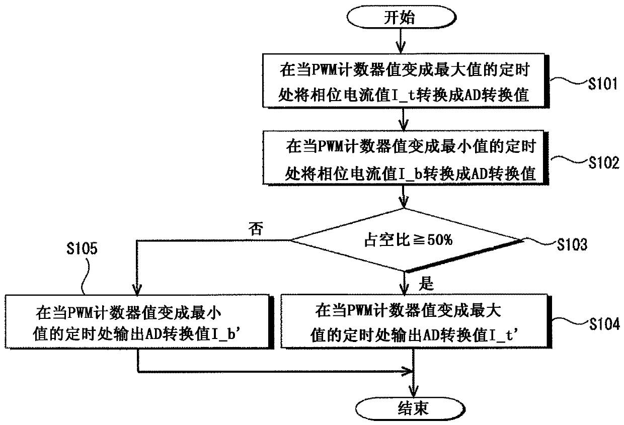
The invention relates to a motor control apparatus, a control method thereof, and a program. The motor control apparatus includes an inverter comprising switching elements; current detection means fordetecting a phase current value output from the inverter to each phase of a three-phase AC motor; conversion means for converting the phase current value into a digital AD conversion value; and modulation means for comparing a phase voltage command value based on the AD conversion value from the conversion means with a PWM counter value generated using a timer operating at predetermined cycles togenerate a PWM signal and outputting the generated PWM signal to the inverter to thereby switch the switching elements of the inverter and control the three-phase AC motor. The conversion means outputs the AD conversion value acquired by converting the phase current value at a timing when a rectangular width of a rectangular wave of a phase voltage value corresponding to the PWM counter value islong.

Description

technical field [0001] The present disclosure relates to a motor control device for controlling a three-phase AC motor, a control method and a program thereof. Background technique [0002] There is known a motor control device which converts a phase current value of a three-phase AC motor detected by a current sensor into a digital AD converted value, generates a current command value based on this converted AD converted value, and controls a three-phase AC based on The current command value of the motor switches the switching elements of the inverter (for example, Japanese Unexamined Patent Application Publication Nos. 2010-148301 and 2008-265645). [0003] The motor control device disclosed in Japanese Unexamined Patent Application Publication No. 2010-148301 corrects a current command value in order to prevent switching noise of the inverter from occurring. However, the present inventors have found a problem that the correction of the current command value may cause the...

Claims


Application Information

Patent Timeline
Patent Type & Authority Applications(China)
IPC IPC(8): H02P21/22H02P27/08
CPCH02P21/22H02P27/08H02P27/085H02P21/50H02P27/14
Inventor 羽多野显佐佐木优奥松美宏井山宽之野村祐喜
Owner TOYOTA JIDOSHA KK
Learn More