
Liquid repellent structure, method of producing the same, liquid ejection head and protective film

a technology of liquid repellent and protective film, which is applied in the field of liquid repellent structure, can solve the problems of high abrasion resistance, high cost of water repellent production, and high production cost, and achieve high abrasion resistance, high repellency, and easy production.

Inactive Publication Date: 2007-07-12
FUJIFILM CORP
View PDF1 Cites 17 Cited by
  • Summary
  • Abstract
  • Description
  • Claims
  • Application Information

AI Technical Summary

Benefits of technology

[0015] The water repellent film in each of JP 2005-23122 A and Non-Patent Document 1 uses a fluorine-containing solution in an organic solvent, so the conditions for producing the honeycomb structure and the composition of the fluorine-containing solution in an organic solvent are limited. Therefore, it is also hard to produce the water repellent films in JP 2005-23122 A and Non-Patent Document 1 at low cost due to a narrow margin of the production conditions.
[0124] The protective films in the seventh and eighth aspects of the present invention each including a support base and the liquid repellent structure in the first or second aspect of the present invention formed on a surface of the support base, enable the contact angle to be increased with respect to water, an organic solvent, oil and the like, thus achieving high repellency. The contact angle can also be increased with respect to a liquid having a surface tension lower than that of water such as a liquid having a surface tension of 40 mN / m or less, thus repelling oil that is a main component of stains to facilitate oil removal. Stains can be thus prevented from being caused by adhesion of fingerprints, sebum, sweat, cosmetics and the like and even if they cause stains, the stains can be easily removed. Since the protective films in the seventh and eighth aspects of the present invention can prevent stains from being caused by fingerprints, sebum, sweat, cosmetics and the like, the protective film can be advantageously used for, for example, a touch panel or a filter to be attached to the surface of any one of various monitors.

Problems solved by technology

Therefore, the water repellent structure requires an expensive production device and a clean environment for its production.
Furthermore, the production process requires patterning, which involves an increase in the number of steps, thus increasing the time and cost for its production.
In the water repellent structure of JP 2000-226570 A, the water repellent film formed on the uneven surface structure has a thickness as small as about 100 nm and the thickness is not sufficient to achieve high abrasion resistance and causes nonnegligible influences of its deterioration with time.
Therefore, the region exposed by one exposing operation is limited, and the patterning operation is hard, for example, in the case where the water repellent structure with a large area is to be formed on a sheet-like support.
Therefore, it is also hard to produce the water repellent films in JP 2005-23122 A and Non-Patent Document 1 at low cost due to a narrow margin of the production conditions.

Method used


Image

  • Liquid repellent structure, method of producing the same, liquid ejection head and protective film
  • Liquid repellent structure, method of producing the same, liquid ejection head and protective film
  • Liquid repellent structure, method of producing the same, liquid ejection head and protective film

Examples


example 1

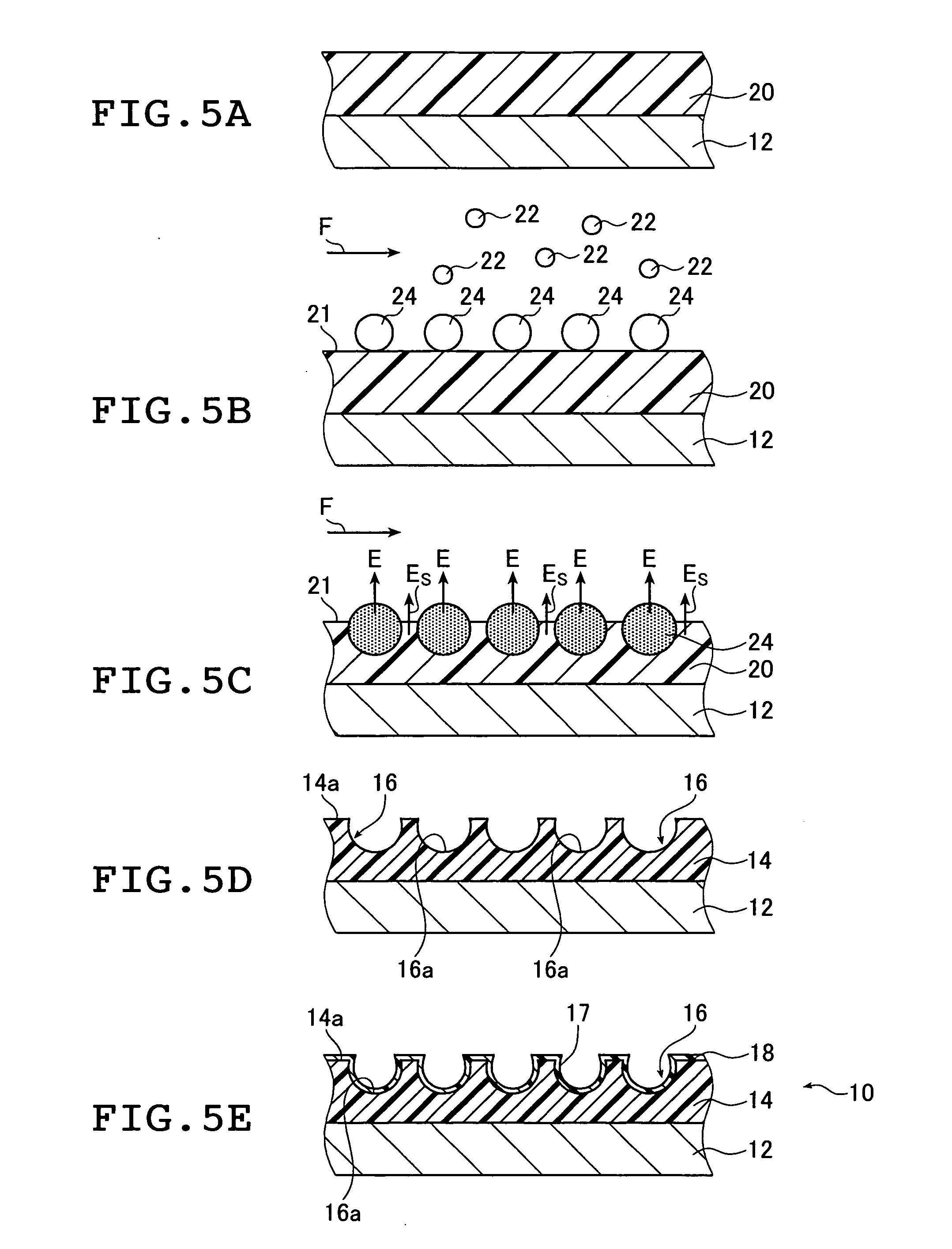
[0309] In Example 1, honeycomb-patterned films (repellency increasing structures) of Example Nos. 1 and 2 to be described below were produced and evaluated for their repellency.

[0310] Poly(ε-caprolactone) was used to form the honeycomb-patterned film in Example No. 1 as shown in FIGS. 10D and 11A.

[0311] The honeycomb-patterned film in Example No. 1 was further subjected to oxygen plasma etching and fluorocarbon coating with a fluoroalkylsilane to form the repellency increasing structure in Example No. 2 as shown in FIGS. 9 and 11B.

[0312] In Example 1, oxygen plasma etching was performed to thin the lateral walls between adjacent recesses thus enlarging the recesses as shown in FIGS. 11A and 11B.

example 2

[0318] Next, Example 2 of the present invention will be described.

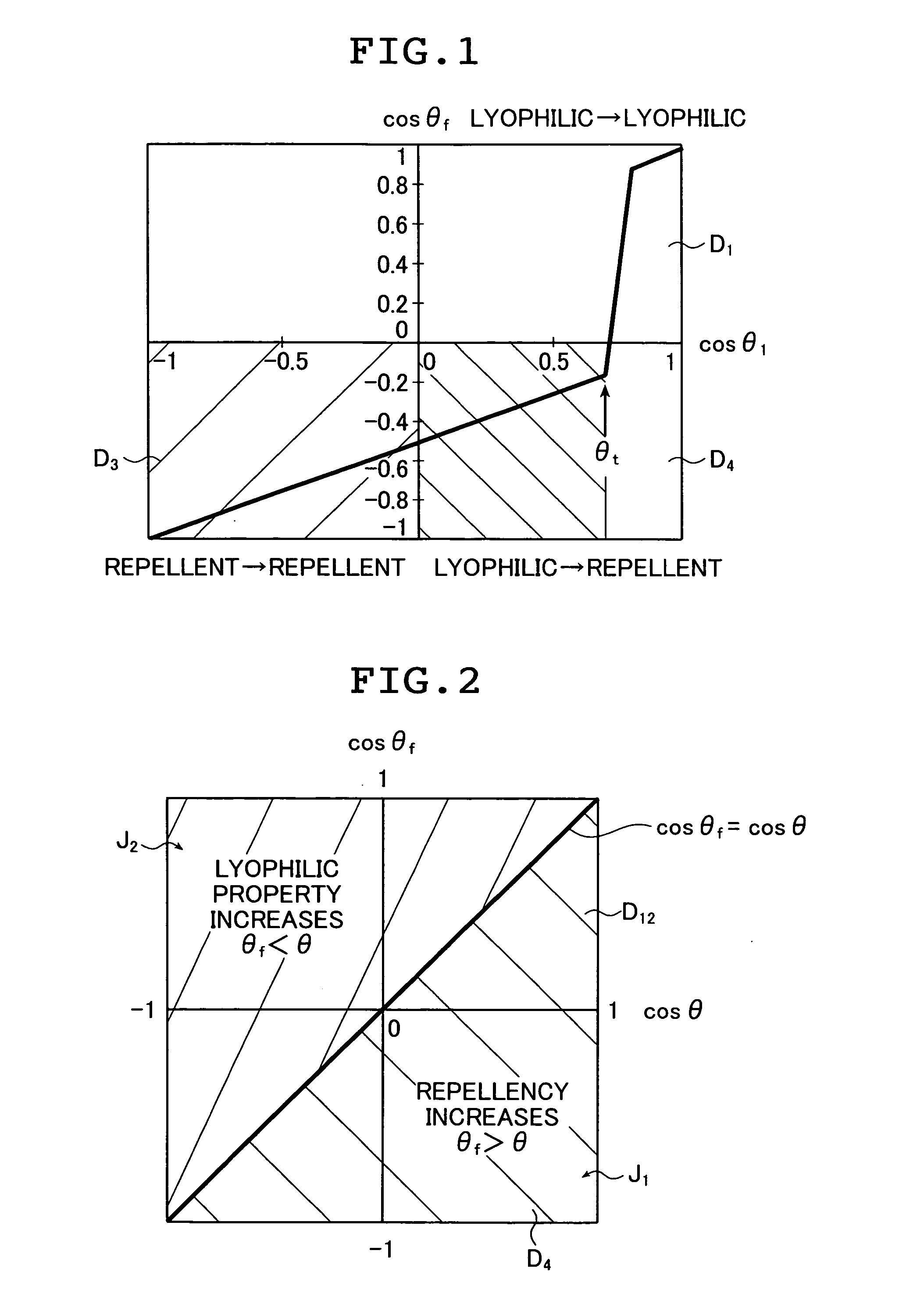
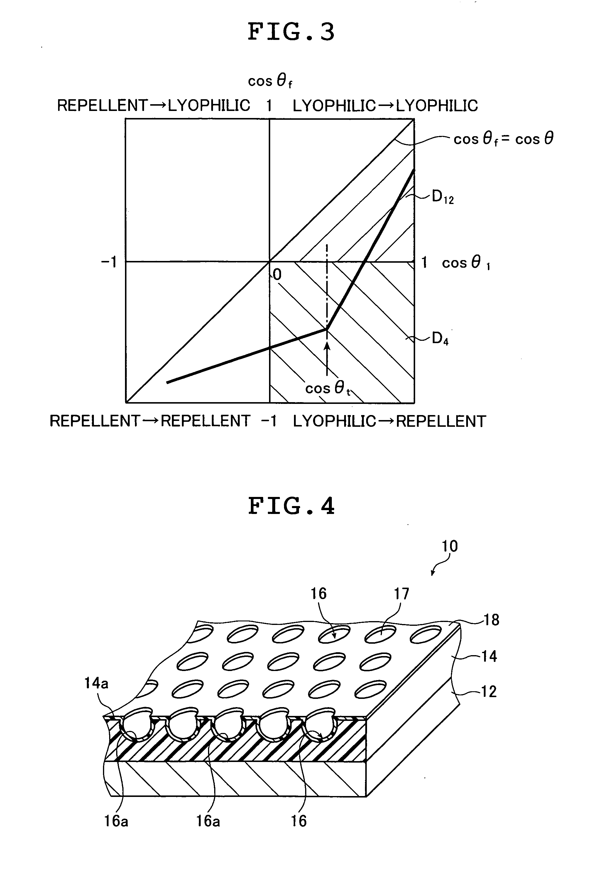
[0319] Various liquids having different surface tensions (water, an aqueous IPA solution having a concentration of 0.5 to 30 wt %, hexadecane, decane, heptane, octane, silicone oil, and a mixed liquid for the wetting tension test (manufactured by Wako Pure Chemical Industries, Ltd.) were used to measure the contact angles in Example Nos. 1 and 2 and Comparative Example Nos. 1 and 2 of Example 1 described above to thereby examine the effect of the surface structure of the present invention. The results are shown in FIGS. 16A and 16B.

[0320]FIG. 16A is a graph showing a relationship between the contact angle on a flat surface in Comparative Example No. 1 and that on the honeycomb structure in Example No. 1 and FIG. 16B is a graph showing a relationship between the contact angle on a flat surface in Comparative Example No. 2 and that on the honeycomb structure in Example No. 2.

[0321] As shown in FIG. 16A, a polygonal l...


PUM

PropertyMeasurementUnit
contact angleaaaaaaaaaa
thicknessaaaaaaaaaa

Abstract

The liquid repellent structure includes a support, and a honeycomb-patterned film and a coating film on the honeycomb-patterned film or a liquid repellent film. The method of producing the structure applies a solution of an organic compound in an organic solvent onto the support, places the support in an atmosphere containing water vapor to form water droplets on a surface of the solution film, evaporates the organic solvent and the droplets to form the honeycomb-patterned film, and forms the coating film made of a fluorine-containing material on a surface of the honeycomb-patterned film or etches the honeycomb-patterned film to form a second honeycomb-patterned film. The liquid ejection head includes an ejection substrate having the liquid repellent structure. The protective film includes a support base and the liquid repellent structure.

Description

[0001] The entire contents of documents cited in this specification are incorporated herein by reference. BACKGROUND OF THE INVENTION [0002] The present invention relates to a liquid repellent structure exhibiting high repellency with respect to liquids such as water, an organic solvent and oil, a method of producing the liquid repellent structure that ensures high productivity, a liquid ejection head using the liquid repellent structure and a stain-resistant protective film. [0003] As for water repellent materials and surface structures obtained from such materials, a contact angle of at least 90° is obtained by using a fluorine-based material. However, a material and a structure exhibiting repellency with respect to a liquid having a low surface tension such as an organic solvent or oil have not been fully examined yet. [0004] Most of the conventionally known repellent materials mainly exhibit repellency with respect to water (also called water repellency). Water repellent materia...

Claims


Application Information

Patent Timeline
Patent Type & Authority Applications(United States)
IPC IPC(8): B32B27/08C23C16/00B05D3/02B05D7/00B05D1/18
CPCB05D1/42B05D3/007Y10T428/1352B41J2/06B05D5/083Y10T428/3154
Inventor KANEKO, YASUHISAITO, KOJUYAMAZAKI, HIDEKAZU
Owner FUJIFILM CORP
Learn More