
Electrode structure

a technology of electrochemical structure and electrode, which is applied in the direction of electrochemical generators, cell components, basic electric elements, etc., can solve the problems of accelerating aging reducing the catalytic reaction performance of the cathodic structure, and unwanted crossover of fuel from the anodic structure throughout the cathodic structure, so as to reduce the total material cost of the fuel cell, increase the output voltage of the fuel cell and power density, and reduce the amount of catalys

Inactive Publication Date: 2007-07-05
IND TECH RES INST
View PDF6 Cites 2 Cited by
  • Summary
  • Abstract
  • Description
  • Claims
  • Application Information

AI Technical Summary

Benefits of technology

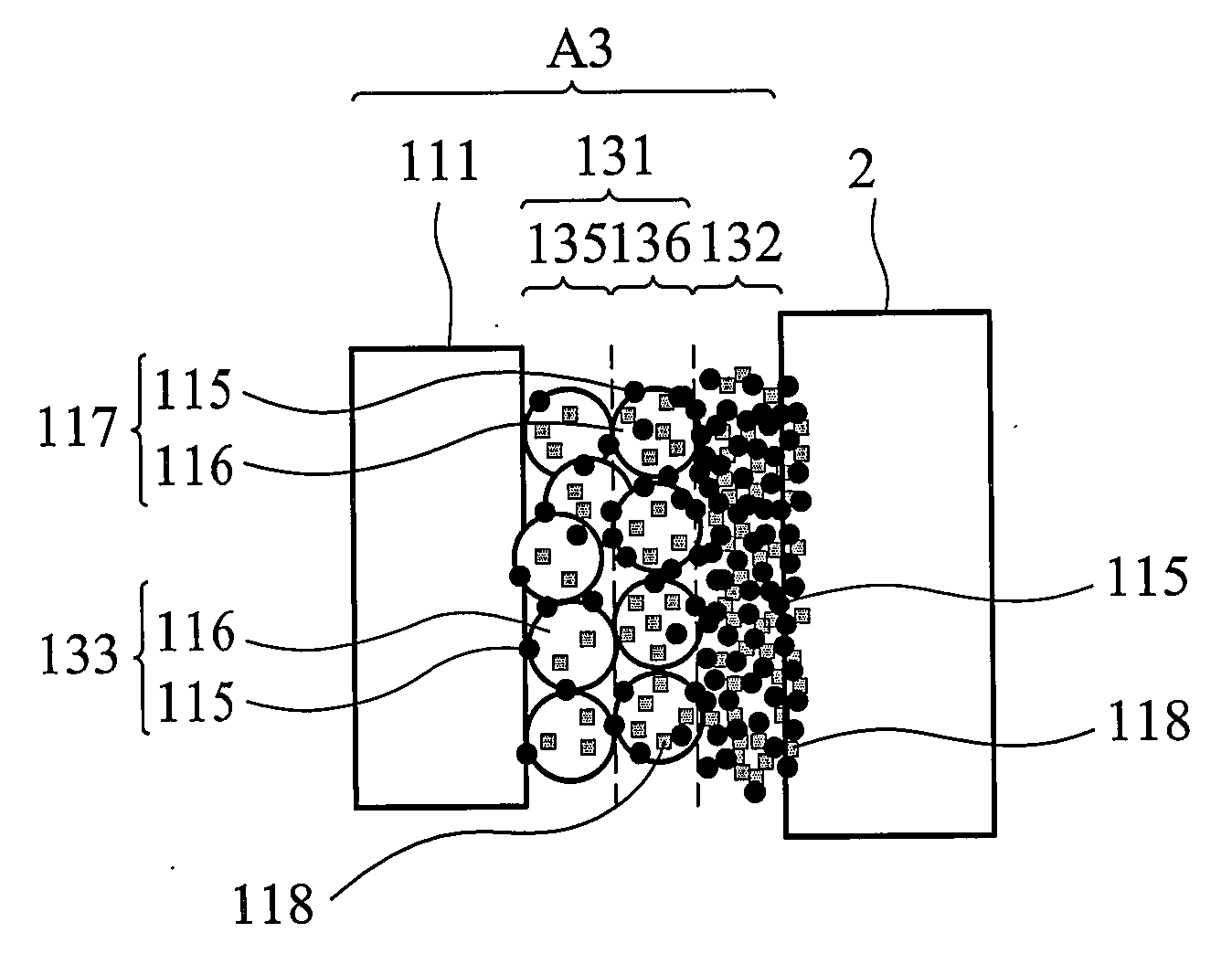
[0012] The aim of the invention at the provides an electrode structure applied to fuel cell, decreased the fuel of the liquid, gel, solid or gaseous organic fuel, e.g. alcohol, aldehyde or acid crossover. It can increase the output voltage of the fuel cell and power density, and than decrease the total material cost of the fuel cell caused by lessen catalyst amount.
[0014] The invention provides an electrode structure having a low fuel crossover and high reaction discharge efficiency with respect to the conventional anode structure, to eliminate aging of the cathode structure.

Problems solved by technology

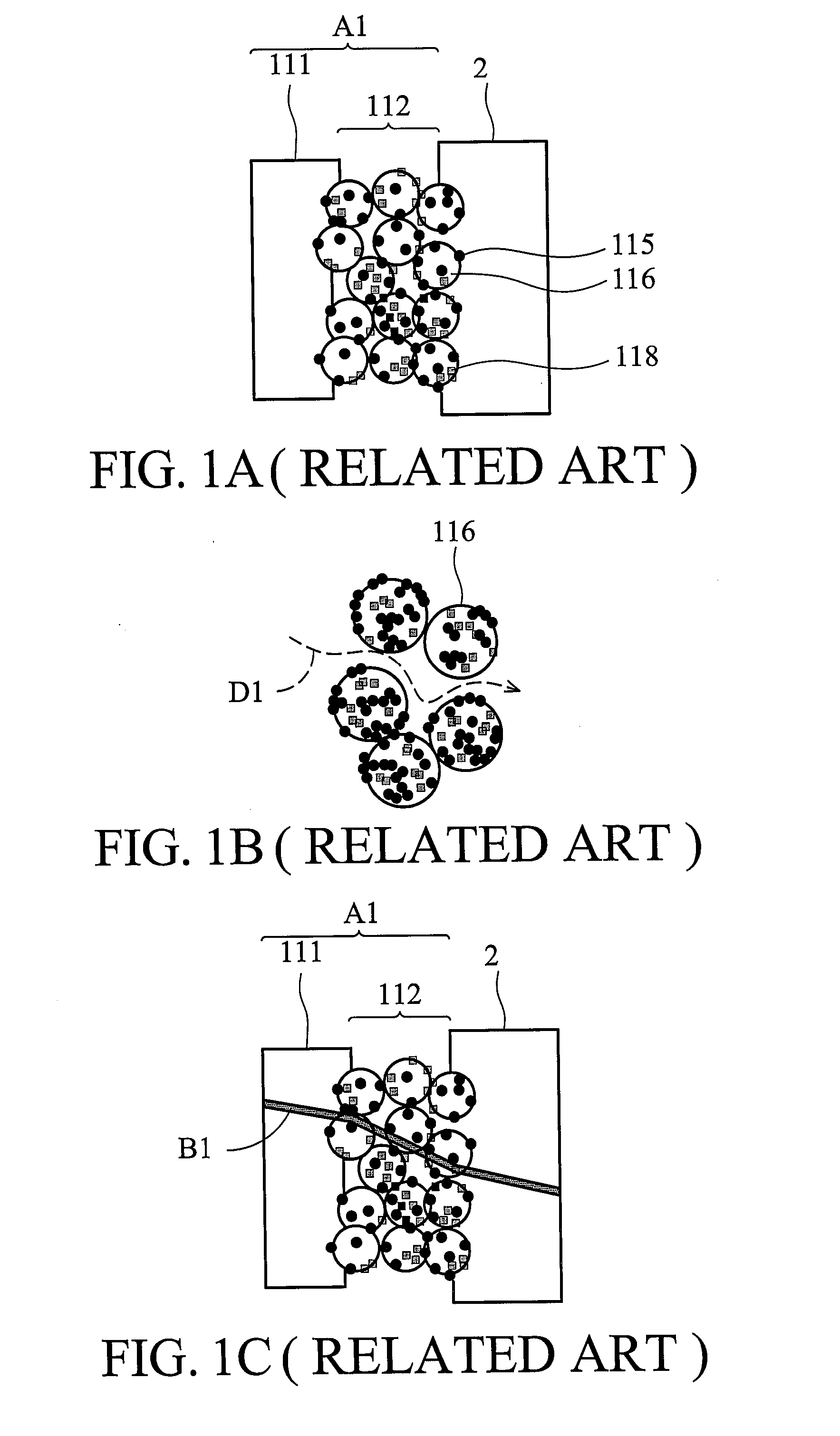
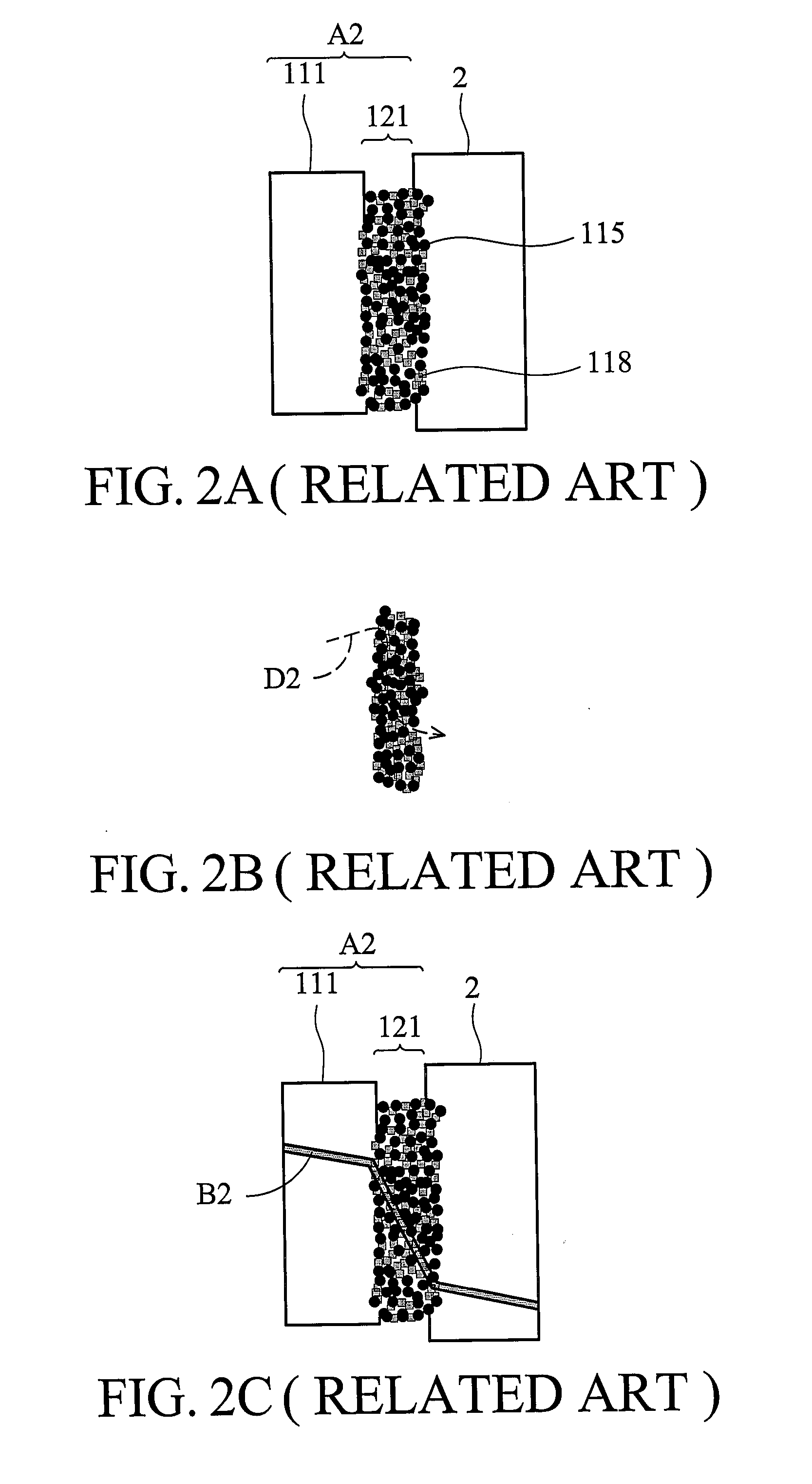
Part of the fuel and water without reacting with the anodic catalyst directly pass through the ionic exchange membrane and reach the cathodic structure, resulting in a decrease of the catalytic reaction performance of the cathodic structure.
Further, crossover of fuel results in the swell of the electrode adhesive between the cathodic electrode and the ionic exchange membrane, thus accelerating aging of the cathodic structure.
It is understood that crossover of the fuel from the anodic structure throughout the cathodic structure is an unwanted situation.

Method used


Image

  • Electrode structure
  • Electrode structure
  • Electrode structure

Examples


Embodiment Construction

[0044] The following description is of the best-contemplated mode of carrying out the invention. This description is made for the purpose of illustrating the general principles of the invention and should not be taken in a limiting sense. The scope of the invention is best determined by reference to the appended claims.

[0045] In FIG. 4, a power generation fuel cell of a first embodiment comprises a fuel (not shown in Figs.) and an electrode structure 100 used to actuate the fuel to generate electricity. The electrode structure 100 sequentially comprises a cathodic structure 72, an ionic exchange membrane 2 disposed next to the cathodic structure 72, and an anodic structure 71. The anodic structure 71 sequentially comprises a first thin platinum alloy black layer 711 disposed next to the ionic exchange membrane 2, a platinum alloy carbon support layer 712 and a first substrate layer 713. The first thin platinum alloy black layer 711 is a thin and dense catalyst layer by a plurality ...


PUM

PropertyMeasurementUnit
catalyticaaaaaaaaaa
conductiveaaaaaaaaaa
anti-corrosiveaaaaaaaaaa

Abstract

An electrode structure of a fuel cell for power generation comprises an anodic structure, a cathodic structure, and an ionic exchange membrane disposed between the anodic and cathodic structures. The anodic and cathodic structures respectively are formed by multi-layer structures, to reduce the fuel crossover from the anodic structure to the cathodic structure, to reduce the catalysts applied amount, and to increase an output electrical energy of the fuel cell. The multi-layer structure of the anodic structure comprises a thin platinum alloy black layer, a Pt alloy layer disposed on the carbon material, and a substrate.

Description

BACKGROUND OF THE INVENTION [0001] 1. Field of the Invention [0002] The invention relates to an electrode structure, and in particular to an electrode structure of a fuel cell for power generation. [0003] 2. Description of the Related Art [0004] In general, fuel cells having an anodic structure, a cathodic structure and an ionic exchange membrane generate power by converting chemical energy to electrical energy by electro-chemical reaction therebetween. In the process of electro-chemical reactions have the fuel oxidation and oxygen reduction. The fuel oxidation reaction of the anodic structure releases hydrogen ions, electrons and carbon dioxides. The oxygen reduction reaction of cathodic structure combines with anodic hydrogen ions, and the electrons releases water. In a conventional fuel cell, however, crossover of the liquid, colloidal, solid or gaseous organic fuel (e.g., alcohol, aldehyde or acid) from the anodic to cathodic structure is inevitable. Part of the fuel and water w...

Claims


Application Information

Patent Timeline
Patent Type & Authority Applications(United States)
IPC IPC(8): H01M4/96H01M8/10H01M4/92
CPCH01M4/8642H01M4/921Y02E60/522H01M8/1004H01M4/926Y02E60/50
Inventor HUANG, CHIU-PINGHSUEH, KAN-LINTSAI, LI-DUANCHANG, SUNG-CHUNWU, FU-CHIYU, DU-YUAN
Owner IND TECH RES INST
Learn More