
Radiotherapeutic device

a radiotherapy and device technology, applied in the direction of therapy, patient positioning for diagnostics, instruments, etc., can solve the problems of not always good for exact identification of various tumors and metastases, excessively complicated methods, and inability to accurately identify tumors and metastases. to achieve the effect of high safety

Inactive Publication Date: 2007-07-05
SIEMENS AG
View PDF19 Cites 40 Cited by
  • Summary
  • Abstract
  • Description
  • Claims
  • Application Information

AI Technical Summary

Benefits of technology

[0010] An object of the present invention is to provide a radiotherapeutic device of the aforementioned type in which the position and the dimensions of tumors or other subjects to be irradiated can be detected in an optimally fast manner with optimally high safety and the irradiation can be implemented very exactly corresponding to this information.
[0012] A significant advantage of the inventive radiotherapeutic device is that it allows a production of exposures of the appertaining body region of the patient by means of a method with which precisely those subjects with which the subsequent irradiation treatment deals can be detected and dimensioned with optimally high precision. The data thereby acquired thus can thereby be (immediately) used in the irradiation without human interactions (which naturally can have errors and time losses associated therewith) being necessary.
[0014] In a further preferred embodiment, the radionuclide emission tomography acquisition unit is a SPECT acquisition unit. The advantage of a SPECT method is that the tracers do not have to be immediately generated on site since they have a significantly longer half-life.
[0020] The radionuclide emission tomography acquisition unit and the computed tomography acquisition unit preferably have a common detector unit. Significant cost savings are thereby possible.
[0023] The coordinate registration device can include a movement sensor system for detection of a movement of the patient positioning device. Manual movements of the support device can also be safely registered with this. Such a movement sensor system has advantages even given an automatic control of the bearing device, since monitoring of the data output by the automatic control device is possible in order to reliably exclude errors that could occur due to incorrect coordinate detection or transfer.
[0024] As mentioned above, the support device can be automatically actuated. The positioning device preferably has a controller in order to activate the actuator coordinated with the irradiation unit. This means that the actuator and the positioning device of the support device are used not only for movement of the patient from the acquisition region into the irradiation region but also are used in order to move the irradiation region (which is typically a very small punctiform region) within the radiotherapeutic irradiation unit relative to the unit, or conversely, to move the patient relative to the irradiation region such that ultimately the entire region to be irradiated (for example a tumor with a very complex shape) is exactly irradiated and destroyed by the shifting of the irradiation region without severely damaging the surrounding tissue.

Problems solved by technology

For this purpose relatively complicated methods are necessary that include complicated markings at or on the patient.
The entire method is not only time- consuming but also is very uncomfortable for the patient.
A problem is that, although computed tomography scans generate very good anatomical images, they are not always good for use for exact identification of various tumors and metastases.
A significant disadvantage of a software-based registration, however is that conventionally it can be implemented only by means of manual interactions of an expert, which requires corresponding personnel and time.
Further uncertainties thereby result, for example the possibility of the patient moving slightly and thus altering his or her position during the long time span between the exposures and the actual treatment.

Method used


Image

  • Radiotherapeutic device
  • Radiotherapeutic device
  • Radiotherapeutic device

Examples


Embodiment Construction

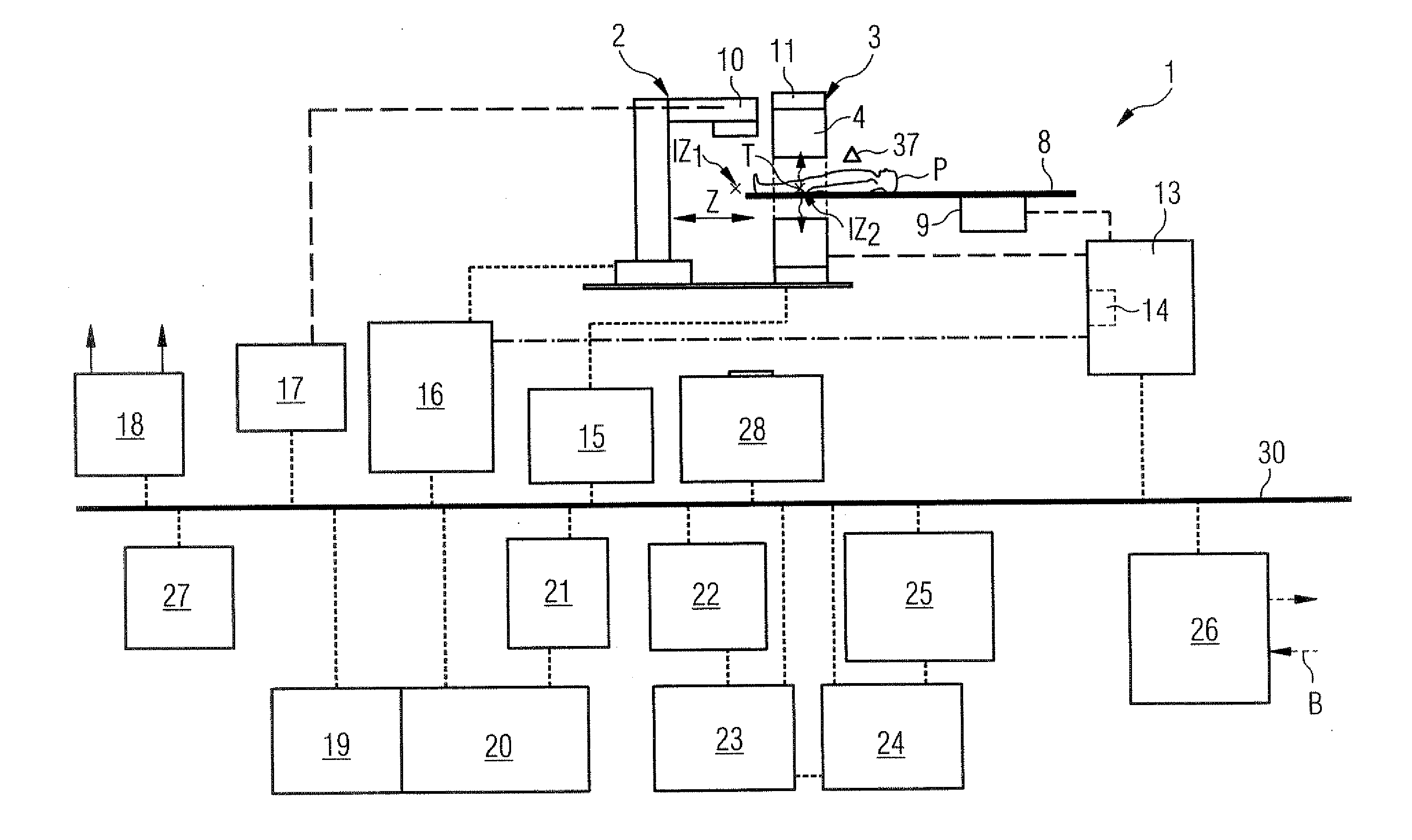
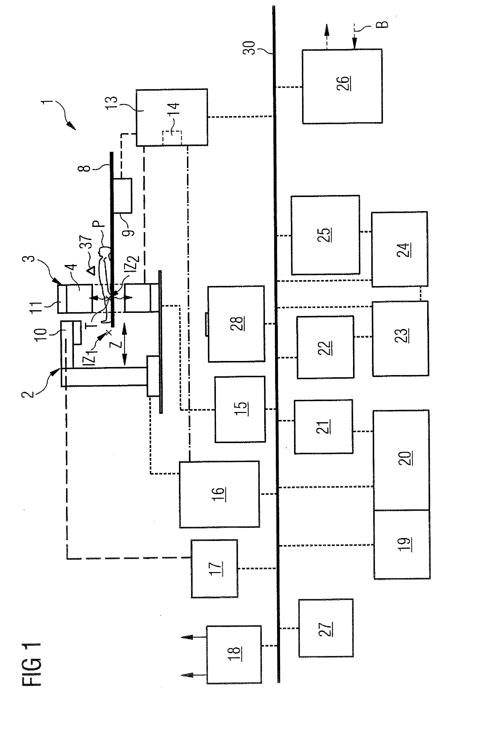
[0030]FIG. 1 is a block diagram of a first exemplary embodiment of an inventive radiotherapeutic device, including peripheral apparatuses.

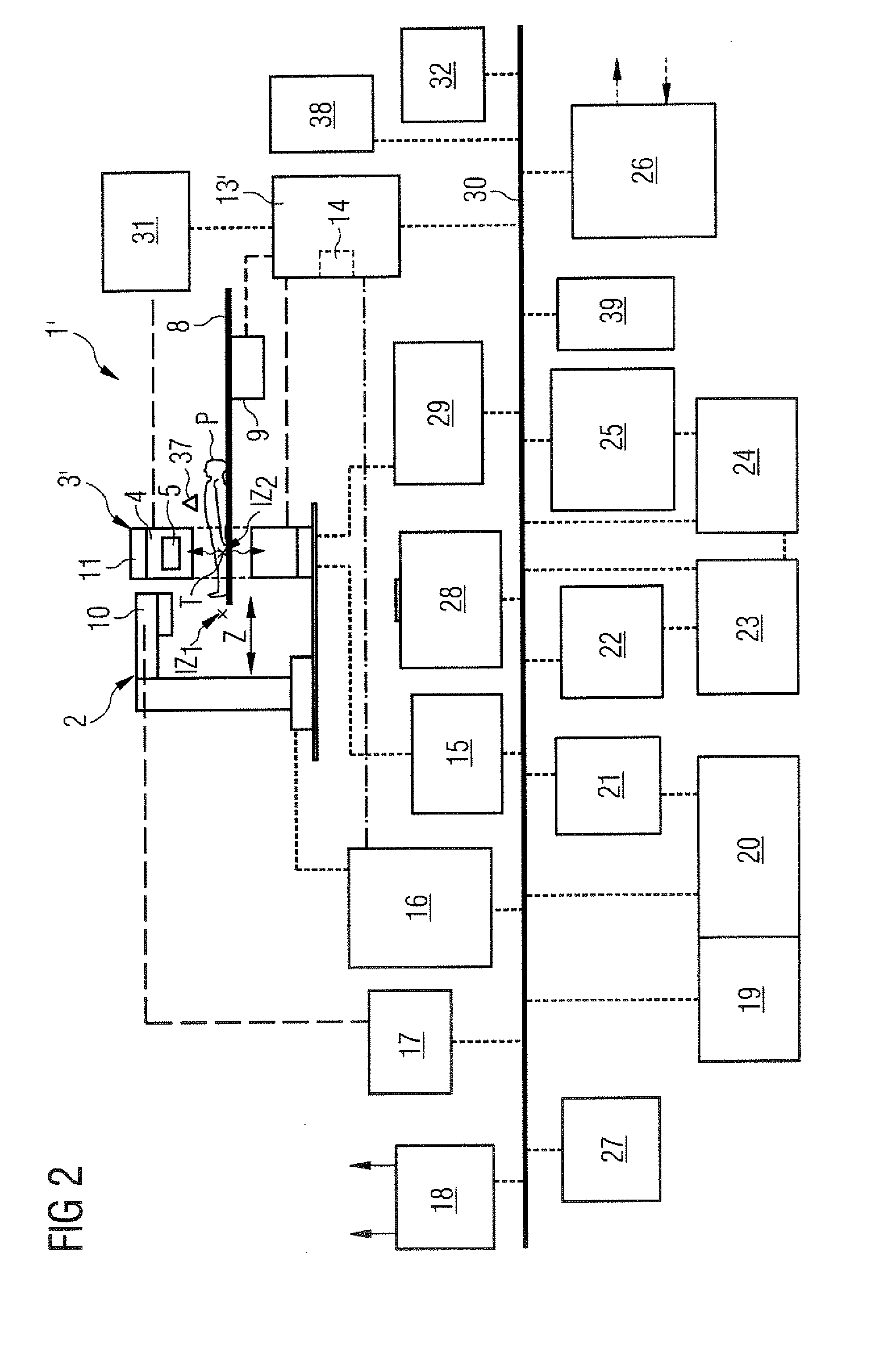
[0031]FIG. 2 is a block diagram of a second exemplary embodiment of an inventive radiotherapeutic device including peripheral apparatuses.

[0032]FIG. 3 shows a third exemplary embodiment of an inventive radiotherapeutic device.

[0033]FIG. 4 schematically illustrates the functional basis of a combined CT / PET acquisition unit according to a first exemplary embodiment.

[0034]FIG. 5 shows the functional basis of a combined CT / PET acquisition unit according to a second exemplary embodiment.

[0035]FIG. 6 shows the temporal relation of the detector readout times and irradiation pulse times in a preferred synchronization of the various actions of the inventive device.

DESCRIPTION OF THE PREFERRED EMBODIMENTS

[0036] In the exemplary embodiment shown in FIG. 1 the radiotherapeutic device 1 has a radiotherapeutic irradiation unit 2 with a linear accelerator ...


PUM


Abstract

A radiotherapeutic device has a radiotherapeutic irradiation unit with a radiation source for generation of radiotherapeutic radiation and a beam guidance and / or beam shaping device in order to direct the radiotherapeutic radiation in a defined manner onto a specific irradiation region. The radiotherapeutic device additionally has an imaging unit that includes a radionuclide emission tomography acquisition unit and a computed tomography scanner. The radiotherapeutic device also has a support device with a positioning device in order to position the support device in an image acquisition position in which a body region to be irradiated of a patient borne on or in the support device is located in an acquisition region of the image acquisition unit, or in order to position the support device in an irradiation position in which the body region to be irradiated of the patient is at least partially located in congruence with the irradiation region of the irradiation unit. The radiotherapeutic device additionally has a coordinate registration device that registers changes of all position coordinates of the support device given a movement of the support device between the image acquisition position and the irradiation position.

Description

BACKGROUND OF THE INVENTION [0001] 1. Field of the Invention [0002] The present invention concerns a radiotherapeutic device of the type having a radiotherapeutic irradiation unit with a radiation source (for example a linear accelerator) for generation of radiotherapeutic radiation, and a beam guidance and / or beam shaping device in order to direct the radiotherapeutic radiation in a defined manner onto a determined irradiation region. [0003] 2. Description of the Prior Art [0004] Worldwide, cancer is the second most common cause of death in the significantly developed countries with a rising tendency in other countries (in particular in Asia). Irradiation therapy of tumors and metastases has been established in cancer therapy for years. In the early years radiation treatments were for the most part implemented using radioactive sources. For some years linear accelerators have been used for this that operate utilizing bremsstrahlung and fast electrons. In addition, there are high vo...

Claims


Application Information

Patent Timeline
IPC IPC(8): A61N5/00H05G1/60
CPCA61B6/032A61B6/037A61B6/04A61B6/541A61B6/547A61B8/0833A61B6/4417A61N5/1037A61N5/1049A61N5/1069A61N2005/1051A61N2005/1061A61N2005/1063A61B8/5238
Inventor MASCHKE, MICHAEL
Owner SIEMENS AG
Learn More