
Optical translation of triangulation position measurement

a triangulation position and optical translation technology, applied in the field of optical translation of triangulation position measurement, can solve the problems of affecting the quality of paper produced, affecting the contact method, and limiting the method

Inactive Publication Date: 2007-06-28
HONEYWELL ASCA INC
View PDF24 Cites 18 Cited by
  • Summary
  • Abstract
  • Description
  • Claims
  • Application Information

AI Technical Summary

Benefits of technology

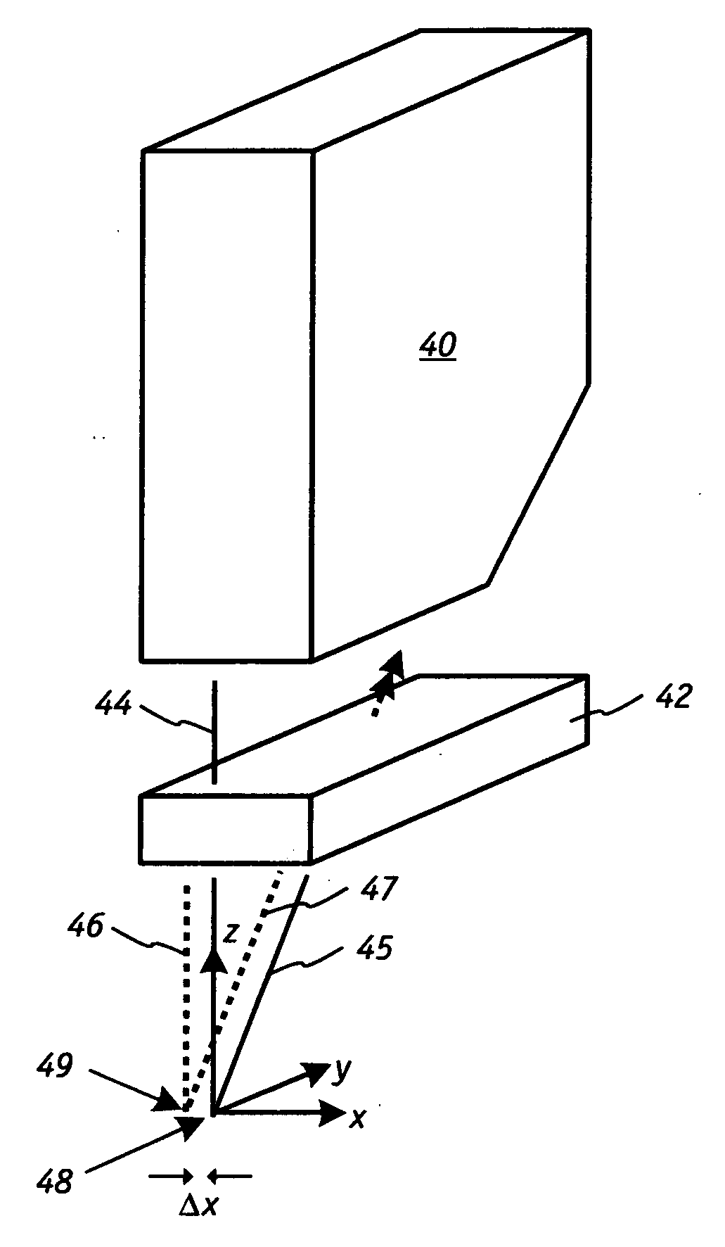
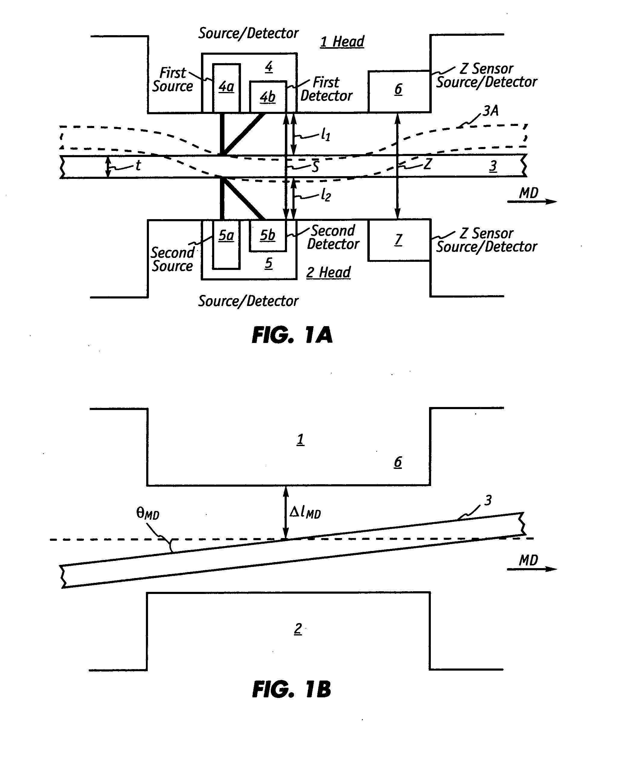
[0012]The present invention is based in part on the development of an optical translation technique for moving the interrogation spot at which a triangulation sensor measures the displacement of a target such as a moving web or sheet of paper. In normal operations of a laser triangulation sensor, an incident laser beam or ray is projected from a sensor head onto a surface of a web that is facing the sensor head. Radiation reflected from the surface is detected or captured by a detector. The distance from the sensor head to the web surface is calculated by triangulation. With the inventive optical translation technique, both the incident ray and the captured ray are translated with one or more transparent substrates, e.g., a plurality of glass geometries, such that the nominal functioning of the triangulation sensor is undisturbed. Optical translation permits adjustments to the interrogation spot without having to physically move the triangulation sensor.
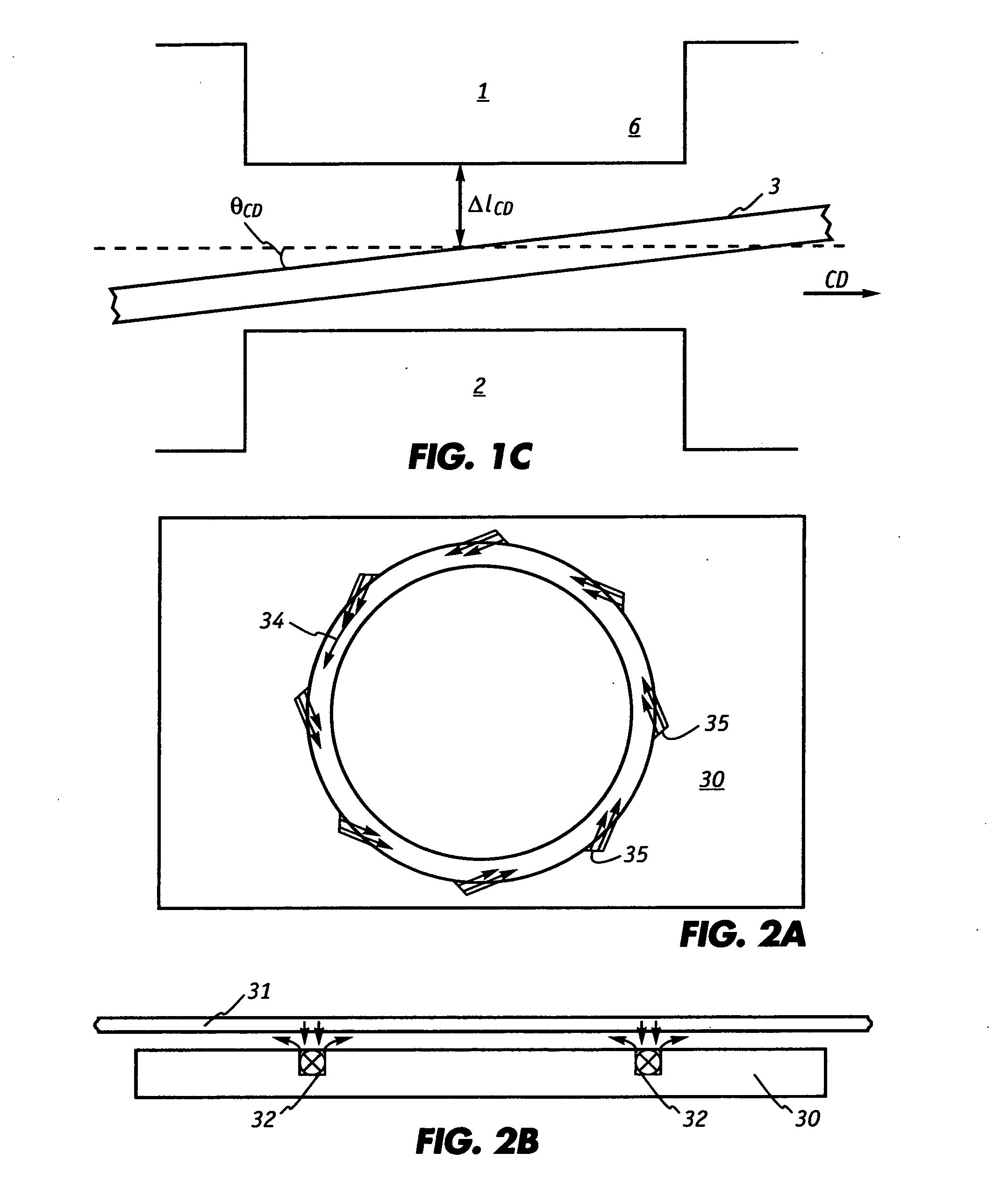
[0013]Caliper sensors employ triangulation sensors to continuously monitor the thickness of a moving or changing target. The caliper sensor can include an air clamp that stabilizes the moving target so the location on the surface, where the interrogation spot of the triangulation sensor is directed, remains stationary to ensure that the caliper sensor yields accurate thickness measurements. During operations of a sheet forming process such as in papermaking, it may be desirable to adjust the traveling paper's position by modifying the force that is exerted on the sheet by the air clamp when practicable taking into consideration the degree of sheet flutter and resistance to tension changes. (In cases, where it is not possible to move the minimum to the desired locations, it would be necessary to physically moving the laser devices.) Once the new position of the sheet has been established, the proper location of the interrogation spot on the sheet can be determined with the inventive optical translation technique. Similarly, should the contour of a moving sheet of paper deviate or shift during operation of the papermaking machine so that the original interrogation spot is no longer at an optimum location, optical translation maneuvers the interrogation spot to a better location without the need to physically move the caliper sensor. In either case, optical translation allows the caliper sensor to function normally without having to physically move the caliper sensor.

Problems solved by technology

Many factors influence the rate at which water is removed which ultimately affects the quality of the paper produced.
Many variations and improvements to these methods exist, but each of the techniques has underlying drawbacks.
The contacting method is subject to three fundamental types of problems.
First, the method can be limited by the strength of the material being measured.
With fragile sheets such as tissue, for example, there is a tendency for the contacting shoes to snag deviations in the sheet surface, causing flaws in the sheet or even causing the sheet to tear.
Second, the sheet itself can damage a contacting caliper sensor due either to abrasive wear on the contacting elements or to physical damage arising during sheet breaks.
For caliper sensors that traverse the sheet, damage can also be caused when the sensor crosses the sheet edge.
Third, the accuracy of contacting sensors can be adversely affected by the buildup of contaminants on the contacting elements, as may occur with coated or filled sheets or sheets containing recycled materials.
The non-contacting inferential thickness measurement methods avoid many of the problems of the contacting methods but are subject to a new set of problems.
However, there are difficulties with previous non-contacting techniques that can limit their usefulness to relatively low-accuracy applications.
One of the problems is that the web may not always be perpendicular to the incident light since the web has a tendency to bounce or develop intermittent wave-like motion.
If the web is non-perpendicular to the incident light and the light beams from two opposing light sources are not directed to exactly the same spot on the sheet, substantial error in measurement can occur.
First, actual web thickness variations from the first laser's measurement spot to the second laser's measurement spot can cause an incorrect thickness measurement.
Second, if the web is not perpendicular to the incident light, the measurement technique will cause an error in the thickness value proportional to the web's angle and to the displacement on the sheet surface between the two measurement spots.
Bouncing or oscillation of the web can further exacerbate this error.
However, it has been discovered that the sheet's surface is not sufficiently planar.
Moreover, it is difficult to change the location of the interrogation spot since that would entail disassembling and physically moving the caliper sensor either upstream or downstream from its original position.

Method used


Image

  • Optical translation of triangulation position measurement
  • Optical translation of triangulation position measurement
  • Optical translation of triangulation position measurement

Examples


Embodiment Construction

[0042]The present invention is directed to novel optical translation techniques that can be applied to any distance measuring device that employs the principle of triangulation. These distance measuring devices include, for example, conventional laser triangulation sensors that have a solid-state laser source that emits a beam onto a point on a surface of a target being measured and a detector that is arranged along an oblique ray that images the laser spot from the point and measures its reflected angle with respect to its optic axis. The invention is particularly suited for incorporation into distance measuring devices to move the interrogation spot on the target being measured. Thus while the invention will be described in relation to a paper thickness or caliper sensor that is equipped with sensor heads with laser triangulation sensors, it is understood that the invention can be employed in other devices and applications as well.

[0043]Non-contacting caliper sensors such as that ...


PUM


Abstract

An optical translation technique for moving the interrogation spot at which a triangulation system measures the displacement of a target is disclosed. In normal operation of the laser triangulation sensor, an incident laser beam is projected from a sensor head onto a surface of a web that is facing the sensor head. Radiation is reflected from the surface and detected by the sensor. The distance from the sensor head to the web surface is calculated by triangulation. With optical translation, both the incident ray path and the captured ray path are translated with a plurality of high refractive index geometries such that the nominal functioning of the triangulation sensor remains undisturbed. The optimal position on the sheet wherein the interrogation spot will be located can be ascertained.

Description

REFERENCE TO RELATED APPLICATIONS[0001]This application claims priority to U.S. Provisional Application 60 / 753,691 that was filed on Dec. 22, 2005.FIELD OF THE INVENTION[0002]The present invention relates generally to techniques for non-contacting thickness or caliper measurements of moving sheets such as paper and more particularly to methods of enabling a single point triangulation caliper sensor to optically translate the spot at which the triangulation system measures the displacement of a target. The invention facilitates optimization of various parameters of the caliper sensor and permits determination of the desired position on a moving sheet where the interrogation spot should be.BACKGROUND OF THE INVENTION[0003]In the manufacture of paper on continuous papermaking machines, a web of paper is formed from an aqueous suspension of fibers (stock) on a traveling mesh papermaking fabric and water drains by gravity and suction through the fabric. The web is then transferred to the...

Claims


Application Information

Patent Timeline
IPC IPC(8): G01N21/86G01V8/00
CPCD21F7/06G01B11/0691G01N21/8983G01S17/48G01S7/497
Inventor DUCK, GRAHAM I.HUGHES, MICHAEL K. Y.
Owner HONEYWELL ASCA INC
Learn More