
Object position independent method to measure the thickness of coatings deposited on curved objects moving at high rates

a technology of moving containers and coatings, applied in the direction of optically investigating flaws/contamination, color/spectral properties measurement, instruments, etc., can solve the problem that the technique is substantially insensitive to ambient light, and achieve the effect of accurate coating thickness measurement and fast detection

Active Publication Date: 2020-09-29
ARKEMA INC
View PDF28 Cites 0 Cited by
  • Summary
  • Abstract
  • Description
  • Claims
  • Application Information

AI Technical Summary

Benefits of technology

[0017]Currently practiced optical thickness measurement method, most commonly using meters supplied by American Glass Research (AGR), provides accurate measurement of thin coating thicknesses (e.g., less than about 20 nm), as well as accurately identifying small changes in coating thickness, for static bottles at near ambient temperatures (e.g., <100° C.) using a direct contact measurement approach using index matching fluid. At the same time, accurate determination of the coating thickness at the “hot end” of the system during the in-line production process is also highly desirable, for example, to maintain the coating within a specified tolerance range and to reduce inventory loss.SUMMARY OF THE INVENTION
[0018]The inventors have developed a non-contact technique for measuring coating thickness on moving objects. Aspects of the technique enable accurate coating thickness measurements on curved surfaces at relatively large distances (e.g., >5 cm) from, for example, a bottle surface to an optical detector setup. The technique relies on fast detection of both reflected and transmitted light, recorded from the surface of the moving object (e.g., moving at <1 m / s). Software identifies the position of a bottle on the time frame of a light beam of less than 5 msec. The technique is substantially insensitive to the ambient light normally present inside a manufacturing facilities such as glass container plants. In some instances, the technique enables measurement of thicknesses of hot objects with surface temperatures of 400-600° C.

Problems solved by technology

The technique is substantially insensitive to the ambient light normally present inside a manufacturing facilities such as glass container plants.

Method used


Image

  • Object position independent method to measure the thickness of coatings deposited on curved objects moving at high rates
  • Object position independent method to measure the thickness of coatings deposited on curved objects moving at high rates
  • Object position independent method to measure the thickness of coatings deposited on curved objects moving at high rates

Examples


example 1

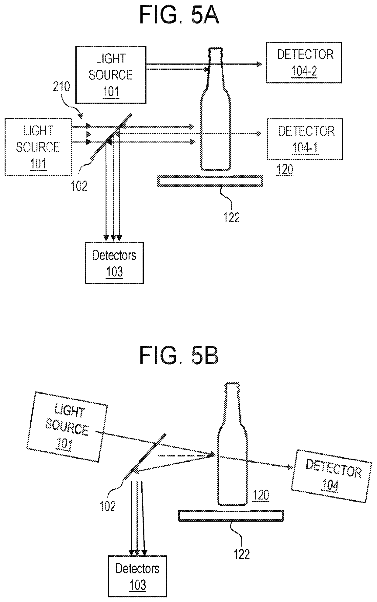
[0066]A light source (101) that may be an LED laser light source (404.6 nm) using a special assembly is directed on the surface of a moving container object. In some instances, it can pass through a beam splitter as shown in FIG. 5A at close to 90 degree angle to the surface of the bottle. In some instances, the laser light can be directed at the container surface at small angle of 0 to 15 degrees to the normal drawn at the container surface with, FIG. 5 B. In some instances of this invention, a detector measuring transmittance of this light is placed behind the container, 104. In some instances, redirection and / or collection optics are used to direct reflected light from the container towards fast detectors. In some cases, the light of a narrow wavelength and / or a series of light sources of narrow wavelength are directed through a hole in a parabolic mirror alignment / collection system, FIG. 6. These light sources may be directed at different angles to the normal of the container su...

example 2

[0069]Using setup similar to that described in Example 1 and without separation of multiple reflections, amber bottles having coating thickness previously measured by standard AGR meter were measured at variable distance from the optical collection / redirection system and the bottle surface. Correlation of the known AGR coating thickness with thickness measured by non-contact detection system of this invention was calculated over two different detector-to-bottle distance ranges. For close detector distance range (7-32 mm) the correlation had R2 value of 98.4%. For farther detector distance range (150-185 mm) the correlation between the two measurements had R2 value of 97.9%. Thus, using current invention similar coating thickness measurement results are readily obtained when detector is up to 20 cm away from bottle as when detector is nearly in contact with container (<1 cm).

example 3

[0070]Several examples of optically calculated coating thickness based on the average intensity of the wavelength channels are presented in FIG. 15 A for reflected light. The data were generated using custom program based on Jones matrix formalism and dispersion parameters of SnO2 coatings on flat soda lime substrates. The thickness of the SnO2 coatings were converted from nanometers into CTU using known conversion relationship (3.45 CTU=1 nm). Four non-polarized wavelength channels are presented in this figure, having peak intensity at 325, 454, 545 and 663 nm were considered. The width for each channel was selected at 1 nm. It is clear that based on the dispersion parameters of the tin dioxide coatings, the intensity of the reflected light increases with the increasing thickness of the coatings, between 0 and 50 CTU. The biggest increased is demonstrated using a 325 nm wavelength channel. For example, maximum to minimum ratios for 325, B, G and R wavelength channels were 3.7, 1.73...


PUM

PropertyMeasurementUnit
thicknessaaaaaaaaaa
thicknessaaaaaaaaaa
thicknessaaaaaaaaaa

Abstract

Methods and apparatus for measuring a thickness of a coating on an moving object are provided. Light is directed toward the object at a predetermined location on the object such that a portion of the light interacts with the object. A I D and / or 2D maximum intensities for at least one wavelength channel is captured that is produced by the portion of the light interacting with the object. A measured average intensity of the wavelength channel and / or intensities and their arithmetic derivatives of multi wavelength channel geometries is converted into I D (averaged) and / or 2D thickness values. Based on these values an acceptability of the coating is evaluated and thickness calculated.

Description

CROSS-REFERENCE TO RELATED APPLICATIONS[0001]This application is a national stage application under 35 U.S.C. § 371 of PCT / US2017 / 012087 filed Jan. 4, 2017, which claims benefit to U.S. patent application Ser. No. 62 / 275,912, filed Jan. 7, 2016.FIELD OF THE INVENTION[0002]The present invention relates to methods and apparatus for optically measuring a thickness of a coating deposited on a moving container during on-line productions.BACKGROUND OF THE INVENTION[0003]During a glass container forming process, a metal-oxide coating is typically applied to the exterior of the glass container. Such coatings, which include tin, titanium, or other reactive metallic compounds, or organometallic compounds, may be employed to protect the glass container from surface damage, such as abrasions and scratches, which result in a loss of tensile strength for the glass container. High tensile strength in a glass container is desirable, particularly when containers are mass produced, move rapidly in cl...

Claims


Application Information

Patent Timeline
Patent Type & Authority Patents(United States)
IPC IPC(8): G01B11/06G01N21/84G01N21/25G01B21/06G01B11/02G01N21/90
CPCG01B11/0633G01N21/8422G01B21/06G01B11/0691G01B11/026G01N21/255G01N2021/8427G01N21/9054
Inventor MOELLER, GUNTER E.KOROTKOV, ROMAN Y.SMITH, RYAN C.
Owner ARKEMA INC
Learn More