
Acetabular cup with rigid fasteners

a technology of acetabular cups and fasteners, which is applied in the field of orthopaedics, can solve the problems of stress on the joints or damage of the body, direct contact with moving bones, and wear of cartilage, so as to improve the fixation effect, and improve the support effect of the body

Inactive Publication Date: 2007-06-21
DEPUY PROD INC
View PDF12 Cites 78 Cited by
  • Summary
  • Abstract
  • Description
  • Claims
  • Application Information

AI Technical Summary

Benefits of technology

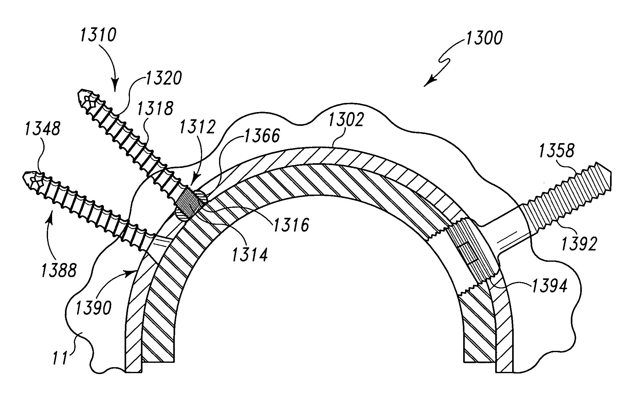
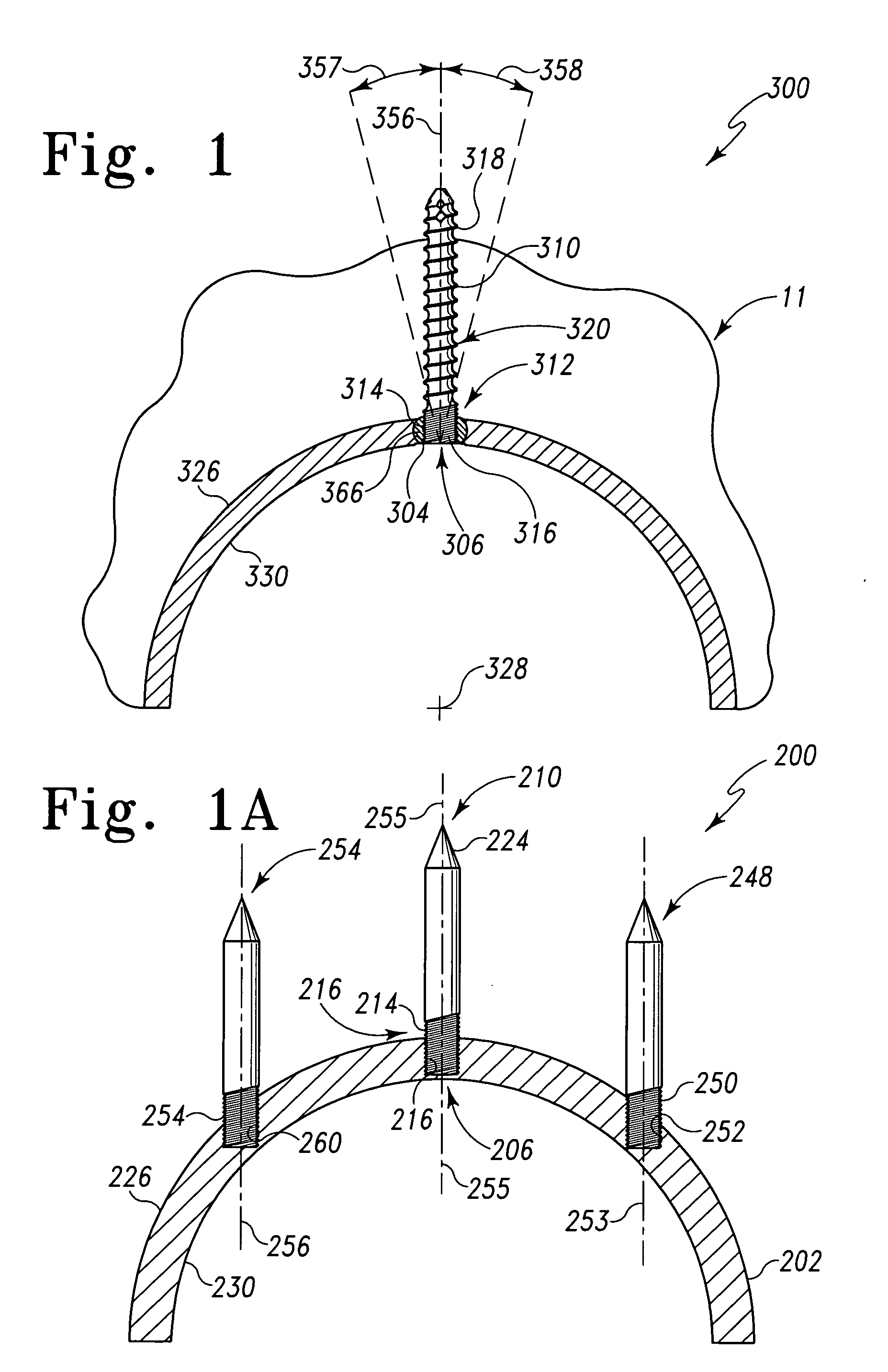
[0020] The locking orthopaedic implant of the assembly may include a screw that locks to the acetabular reconstruction device in a single orientation relative to the device. Alternatively, the fastener may be in the form of a screw or a pin that may lock to the reconstruction device in any one of infinite orientations with respect to the device. Such variable orientations of a locking fastener may be accomplished by one of many devices such as by using polyaxial bushing technology. The polyaxial bushing has a generally spherical outer diameter “OD” and a tapered cylindrical inner diameter “ID.” The bushing is split readily so that it may compress upon the insertion of a fastener through the tapered bore. The fastener expands the tapered bore causing the spherical periphery of the bushing to lockably engage with the spherical bore on the orthopaedic implant.
[0034] The technical advantages of the present invention further include the ability to provide better fixation if significant defects are found in the bone adjoining the orthopaedic joint implant. For example, according to another aspect of the present invention, an orthopaedic joint assembly for attachment to a bone is provided. The joint assembly includes a body having an anterior wall defining an opening in the body. The joint assembly also includes a fastener having a portion of the fastener fitted through the opening of the body. The fastener is rigidly connected to the body. Thus the present invention provides for better fixation if significant defects occur by permitting the fastener to better support the body by being rigidly attached to the body.
[0035] The technical advantages of the present invention also include an ability to provide better fixation to poor quality bone. For example, according to another aspect of the present invention, an orthopaedic joint assembly for attachment to bone is provided. The joint assembly includes an orthopaedic joint component having an interior wall defining an opening in the body. The joint assembly also includes a fastener having a portion fitted through the opening of the orthopaedic joint component. The fastener is rigidly connected to the orthopaedic joint component. Thus the present invention provides for better fixation of the orthopaedic implant component to bone when poor quality bone is positioned near the joint.
[0036] The technical advantages of the present invention also include the ability to provide more options to achieve bone fixation in sub-optimum bone conditions, where the patient may have good bone quality in certain locations and poor bone quality in other locations. For example, according to another aspect of the present invention, an orthopaedic joint component is provided for attachment to a bone. The orthopaedic joint component has an interior wall defining an opening in the component. The joint assembly also includes a fastener having a portion rigidly connected to the body in a selected one of a plurality of angular positions relative to the orthopaedic component. Thus the present invention provides for more options to achieve bone fixation by permitting the fastener to be rigidly positioned in one of several positions in order that the fastener is aligned with better quality bone rather than with poor quality bone.
[0037] The technical advantages of the present invention also include the ability to keep the orthopaedic joint component stable. For example, according to another aspect of the present invention, an orthopaedic joint assembly for attachment to bone is provided. The joint assembly includes an orthopaedic joint component having an interior wall defining a component opening in the component. The joint assembly also includes a fastener having a portion of the fastener fitted through the opening of the component. The fastener is rigidly connected to the component. Thus the present invention provides for a rigid fastener to keep the acetabular device stable in the bone.
[0038] The technical advantages of the present invention further include the ability to compensate for the resorption of bone over time behind the orthopaedic joint component. For example, according to another aspect of the present invention, an. orthopaedic joint assembly is provided for attachment to a bone. The joint assembly includes a joint component having an interior wall defining an opening in the joint component. The joint assembly also includes a fastener having a portion of the fastener fitted through the opening of the component. The fastener is rigidly connected to the component providing a rigid construct that provides support for the orthopaedic joint component when resorption of bone around the component occurs.

Problems solved by technology

The joints in the body are stressed or can be damaged in a variety of ways.
Over time, the normal use of a joint may wear down the cartilage and bring the moving bones in direct contact with each other.
In contrast, in normal use, a trauma to a joint, such as the delivery of a large force, from an accident for, example, an automobile accident, may cause considerable damage to the bones, the cartilage or to other connective tissue such as tendons or ligaments.
However, the fixation of the acetabulum component of the orthopaedic hip joint does not have the benefit of fitting to a medullary canal.
However, for those patients in which the pelvic bone is of poor quality or includes significant defects, the fixation of the hip cup to the acetabulum may not be secure.

Method used


Image

  • Acetabular cup with rigid fasteners
  • Acetabular cup with rigid fasteners
  • Acetabular cup with rigid fasteners

Examples


Embodiment Construction

[0089] Embodiments of the present invention and the advantages thereof are best understood by referring to the following descriptions and drawings, wherein like numerals are used for like and corresponding parts of the drawings.

[0090] According to the present invention and referring now to FIG. 4, an orthopaedic implant joint assembly 100 is shown. The orthopaedic implant joint assembly 100 may be any orthopaedic reconstruction joint in the human anatomy. For example, the orthopaedic implant joint assembly 100 may be a hip stem, a femoral knee component, a tibial knee, a humeral shoulder, a glenoid shoulder, a wrist component, elbow component, or an ankle component. It should be appreciated that the orthopaedic joint assembly may be an assembly of any orthopaedic implant joint component and a fastener.

[0091] The orthopaedic joint assembly 100 includes a body 102. The body 102 may be in the form of any orthopaedic joint component. For example, the body 102 may be a hip stem, a hip ...


PUM


Abstract

An acetabular cup assembly for attachment to an acetabulum is provided. The cup includes a body having an interior wall and defining an opening in the body. The cup also includes a fastener having a portion thereof fitted through the opening of the body. The fastener is rigidly connected to the body.

Description

CROSS-REFERENCE TO RELATED APPLICATIONS [0001] Cross-reference is made to the following applications: DEP5608 titled, “ORTHOPAEDIC JOINT ASSEMBLY WITH RIGIDLY LOCKED FASTENER, KIT AND ASSOCIATED METHOD” and DEP5609 titled “MODULAR HIP CUP ASSEMBLY, FASTENER ASSEMBLY AND FASTENER” filed concurrently herewith which are incorporated herein by reference.TECHNICAL FIELD OF THE INVENTION [0002] The present invention relates generally to the field of orthopaedics, and more particularly, to a device for securing a prosthetic component to bone for use in orthopaedic trauma or orthopaedic joint products. BACKGROUND OF THE INVENTION [0003] The skeletal system includes many long bones that extend from the human torso. These long bones include the femur, fibula, tibia, humerus, radius and ulna. [0004] A joint within the human body forms a juncture between two or more bones or other skeletal parts. The ankle, hip, knee, shoulder, elbow and wrist are just a few examples of the multitude of joints ...

Claims


Application Information

Patent Timeline
Patent Type & Authority Applications(United States)
IPC IPC(8): A61F2/34A61F2/36
CPCA61B17/8047A61B17/86A61B17/8605A61F2/30721A61F2/30767A61F2/32A61F2/34A61F2/36A61F2/3662A61F2/38A61F2/3804A61F2/3859A61F2/389A61F2/40A61F2/4059A61F2/4081A61F2/4202A61F2/4261A61F2002/30332A61F2002/30378A61F2002/30405A61F2002/30408A61F2002/30416A61F2002/30418A61F2002/30507A61F2002/30538A61F2002/30578A61F2002/30774A61F2002/30787A61F2002/30792A61F2002/30794A61F2002/30797A61F2002/30808A61F2002/30841A61F2002/30878A61F2002/30892A61F2002/3401A61F2002/3403A61F2002/3404A61F2002/3611A61F2002/3625A61F2002/365A61F2002/4018A61F2002/4037A61F2220/0025A61F2220/0033A61F2250/0006A61F2310/00011A61F2310/00179A61F2002/3079
Inventor LEWIS, PAUL PETER PHILLIPCHRISTIE, MICHAEL J.HUGATE, RONALD R. JR.
Owner DEPUY PROD INC
Learn More