
Mitral valve device using conditioned shape memory alloy

a technology of conditioned shape and alloy, which is applied in the field of mitral valve devices using conditioned shape memory alloy, can solve the problems of devices changing to austenite states, and achieve the effect of sufficient radial stiffness and reduced friction effects

Active Publication Date: 2007-06-14
CARDIAC DIMENSIONS
View PDF99 Cites 12 Cited by
  • Summary
  • Abstract
  • Description
  • Claims
  • Application Information

AI Technical Summary

Benefits of technology

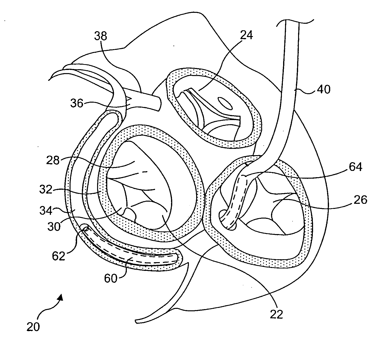
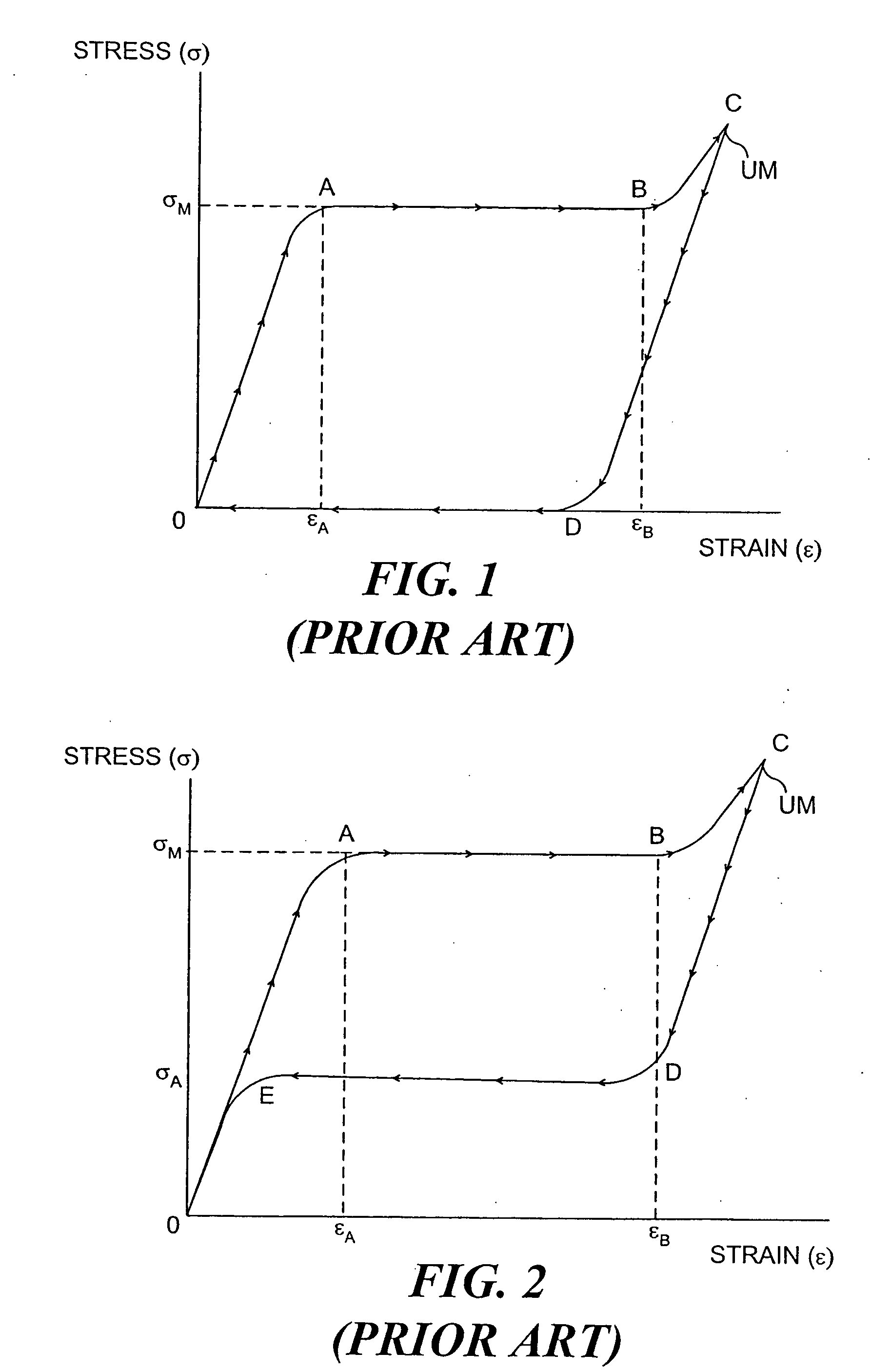
[0026] According to the present invention, a device for treatment of mitral insufficiency is sized so as to be capable of insertion into the coronary sinus and is formed at least in part of an SMA having two states. In a first state, the device has a shape adaptable to fit the shape of the coronary sinus, but when allowed to transform to the second state, the device assumes a second shape that enables a force to be applied to modify the mitral valve annulus in a way that reduces mitral valve regurgitation. The transformation from the first shape to the second shape is facilitated at least partially by utilizing the release of strain energy as the device or a portion thereof is unconstrained and allowed to change from a state of UM to a lower strain condition. Thus, the device may change to an austenite state upon being unloaded. UM is generally induced at strain levels above about 1.0%, and more typically, at strain levels above about 1.5%.
[0033] An optimal method to use the above-described device includes deploying the device and then assisting it into a more optimal shape using a drawstring (tether) or other element, to vary the length of the device along one side and thereby cause a curvature enhancement of the device. This mechanical assistance will alter the stiffness and enhance performance of the device by utilizing the BM effect of UM, as described above.
[0036] Still another aspect of the present invention is directed to a construction in which a mitral annulus shaping device can be constrained in a strained configuration for delivery into the coronary sinus within a hollow member, such as a catheter. A suitable catheter might be formed, for example, from a polymeric material that constrains the mitral annulus shaping device while disposed in the catheter, and which facilitates discharge of the mitral valve annulus reshaping device from the catheter.
[0038] The configuration of the delivery device is selected so that it can properly contain the mitral valve annulus reshaping device and withstand the elastic forces exerted by the device prior to discharge from the delivery device. Preferably, the delivery device has a minimum wall thickness necessary to satisfy these criteria. A constraint provided according to the present invention has the advantage of being thin-walled and flexible in bending, while also having sufficient radial stiffness to be able to withstand the forces exerted by the mitral annulus shaping device as it attempts to recover, even when these forces are applied over a long period of time, at temperatures above body temperature.

Problems solved by technology

Thus, the device may change to an austenite state upon being unloaded.

Method used


Image

  • Mitral valve device using conditioned shape memory alloy
  • Mitral valve device using conditioned shape memory alloy
  • Mitral valve device using conditioned shape memory alloy

Examples


Embodiment Construction

[0059] To understand the present invention, it is necessary to understand austenite to martensite transformations that occur in a SMA and understand how SMA can be used advantageously in the coronary sinus for modifying the mitral valve annulus. After discussing these concepts, the disclosure will turn to specific devices, methods and assemblies of the present invention.

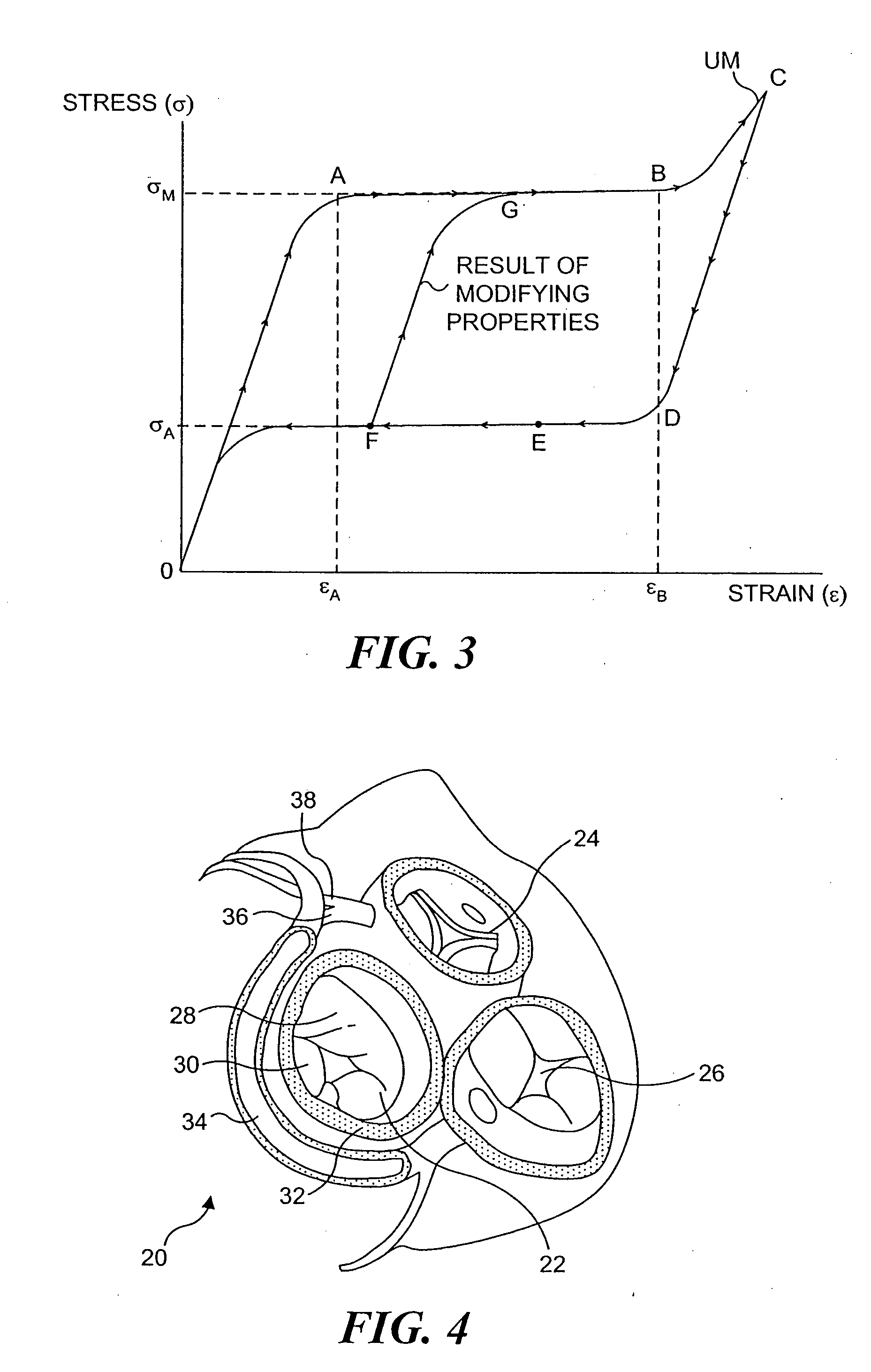
[0060]FIGS. 1-3 illustrate stress-strain curves for martensite-austenitic conversion of an SMA. In these Figures, the SMA is warmed to human body temperature (herein considered to be about 37° C.), which is between Ms and Md for the SMA, so that the SMA is initially austenitic. The following discussion assumes that Ms is equal to Mf, and that As is equal to Af. FIG. 1 shows the case when the As temperature is adjusted higher than 37° C., so that any martensite formed by an applied stress is stable; while FIGS. 2 and 3 show cases where the Af temperature is adjusted below 37° C., so that austenite, at zero stress, is...


PUM


Abstract

A mitral valve annulus reshaping device includes at least a portion that is formed of a biocompatible shape memory alloy SMA having a characteristic temperature, Af, that is preferably below body temperature. The device is constrained in an unstable martensite (UM) state while being introduced through a catheter that passes through the venous system and into the coronary sinus of the heart. The reshaping device is deployed adjacent to the mitral valve annulus of the heart as it is forced from the catheter. When released from the constraint of the catheter, the SMA of the device at least partially converts from the UM state to an austenitic state and attempts to change to a programmed shape that exerts a force on the adjacent tissue and modifies the shape of the annulus. The strain of the SMA can be varied when the device is within the coronary sinus.

Description

CROSS REFERENCE TO RELATED APPLICATIONS [0001] This application is a continuation of pending U.S. application Ser. No. 10 / 359,016, filed Feb. 3, 2003, entitled “Mitral Valve Device Using Conditioned Shape Memory Alloy,” which application is incorporated by reference as if fully set forth herein.INCORPORATION BY REFERENCE [0002] All publications and patent applications mentioned in this specification are herein incorporated by reference to the same extent as if each individual publication or patent application was specifically and individually indicated to be incorporated by reference FIELD OF THE INVENTION [0003] The present invention generally pertains apparatus and a method for treating mitral insufficiency and, more specifically, for treating dilation of the mitral valve annulus of the human heart and concomitant blood leakage, by using force applied with a device formed at least in part of a shape memory alloy that is conditioned to a martensite state before being inserted into ...

Claims


Application Information

Patent Timeline
IPC IPC(8): A61F2/24
CPCA61F2/2451A61F2210/0023
Inventor MATHIS, MARK L.
Owner CARDIAC DIMENSIONS
Learn More