
Method as to work on a part to be finished and a finished part

a technology of working on parts and finished parts, applied in the field of working on finished parts, can solve the problems of scrapping of final parts, failure to achieve the quality criteria, and failure of functional surfaces to meet the needs of quality criteria

Inactive Publication Date: 2011-03-03
MANAGEMENT TOOLBOX GMBH
View PDF7 Cites 0 Cited by
  • Summary
  • Abstract
  • Description
  • Claims
  • Application Information

AI Technical Summary

Benefits of technology

An underlying task of the present disclosure is therefore to present a method of reducing the above mentioned disadvantages.
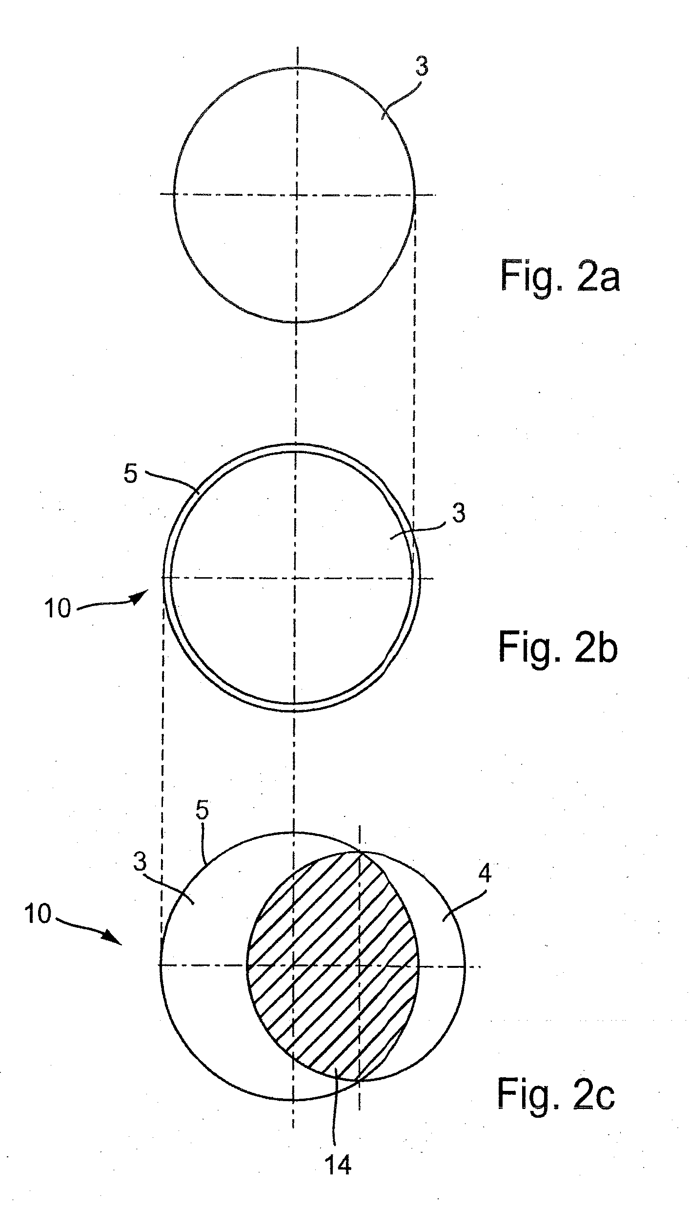
Both 3-dimensional data files, e.g. the virtual file of the “to-be” body and the virtual file of the “as-is” part, will be fitted into each other in a virtual manner. This is done by shifting the virtual “to-be” body into the virtual “as-is” body based on the recorded distance data and position data. The reference points and the fixture positions will be adjusted as needed. By varying the relative positions of both virtual bodies and through calculating the maximum virtual intersection we can make sure that too small wall thicknesses of the final part will be kept to a minimum after machining. It is of special advantage with this method that the relative position of the final part and the raw part is optimized for machining.
To capture the geometry of the raw part we can for example scan (while touching the raw part) different reference points and the material imperfections we can capture for example by using ultrasonic testing or X-raying. It is however preferred a further development of the method by catching the external geometry with a scanner (non-touching). This allows a cost effective and fast capture of the geometry of the raw part. It is of advantage if in this latter case the scanner is led by a robot, allowing scanning the “as-is” body in a clamped position, e.g. we don't need to clamp again after the scanning. This improves the exactness further on.
Finally it is planned to use this method on a raw part being a casting. It is especially of advantage that this invented method is applied on a raw part, where we typically find material imperfections—applying this method ensures a high degree of exactness of the geometry as well as the surface quality of functional surfaces is improved.

Problems solved by technology

However this is not successful if the imperfection are large.
Hence, functional surfaces do not achieve the needed quality criteria and the final part has to be scrapped.
It is also quite ponderous to adjust the raw part into a tooling machine as to machine the final part completely.
This leads to smaller wall thicknesses or even to holes in the finished part.

Method used


Image

  • Method as to work on a part to be finished and a finished part
  • Method as to work on a part to be finished and a finished part
  • Method as to work on a part to be finished and a finished part

Examples


Embodiment Construction

The following description is merely exemplary in nature and is not intended to limit the present disclosure, application, or uses.

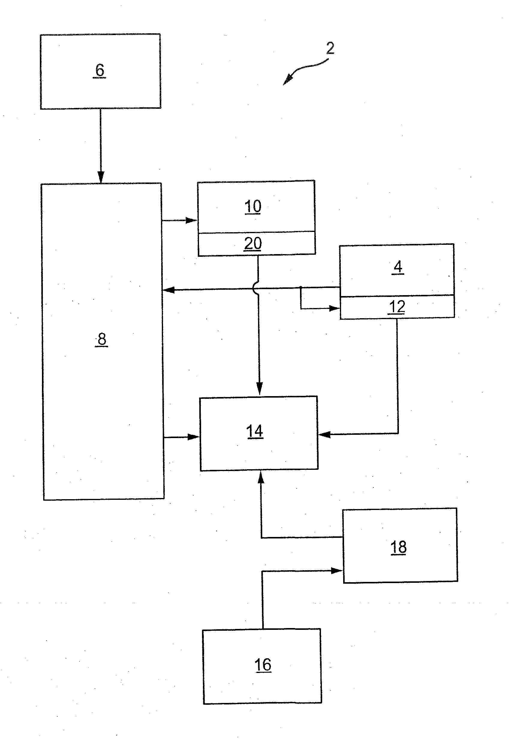
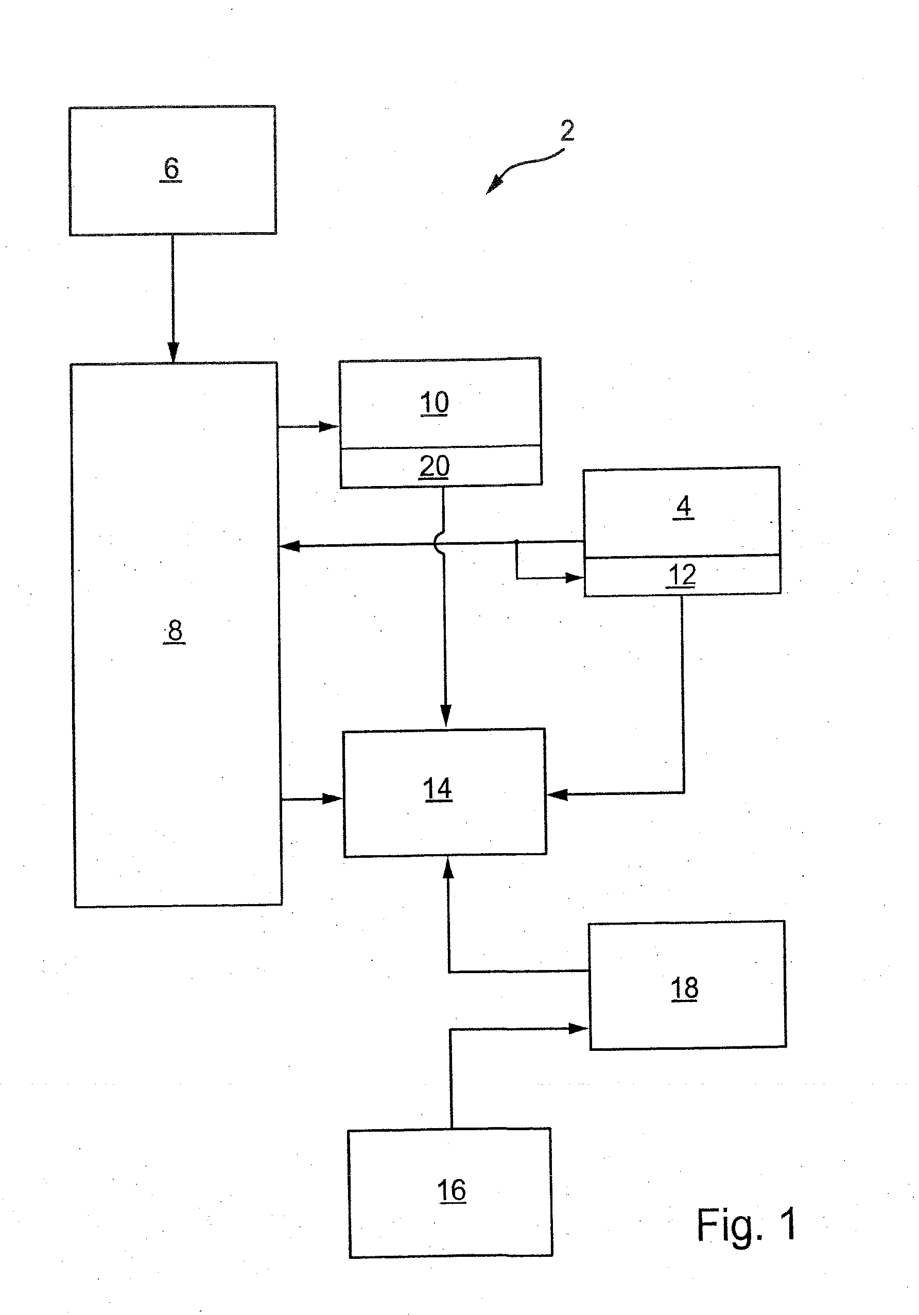
The drawings show in a schematic way a method 2 to machine a product. The product will be machined out of a raw part 3 which at least has to be machined surface and an allowance 5. The method 2 utilizes a virtual “to-be” body 4 being stored electronically as a 3D-datafile, and in one form as a 3D-CAD-datafile. The “to-be” body 4 is here a virtual representation of the latter product being the result of machining. In a first step of the process we capture the geometry of the raw part 3 as well as we capture the local position within the tooling machine, for example by usage of a scanner 6. The recorded data will be transmitted to a computer 8 being stored as “as-is” body 10. The computer 8 adds in the following step an allowance 12 onto the “to-be” body 4. Virtual “as-is” body 10 and virtual “to-be” body 4 now will be fitted into each other in a virtual ma...


PUM


Abstract

The present disclosure provides a method to machine a “to-be” body out of a raw part having at least one functional surface needing an allowance, whereas the method incorporates a “to-be” body, with the following process steps:Capture the geometry of the raw body and its local position within a tooling machine and determine a virtual “as-is” body;Make provision of a virtual allowance onto the virtual “to-be” body;Virtually merge the virtual “as-is” body with the virtual “to-be” body; andCalculate a virtual intersection of the virtual “as-is” body and the virtual “to-be” body and vary the relative position to each other such that the virtual intersection becomes a maximum.

Description

FIELDThe disclosure is concerned with a method as to work on a finished part, a finished part being produced according certain methods, and the finished part itself.BACKGROUNDThe statements in this section merely provide background information related to the present disclosure and may not constitute prior art.While working with a row part one has to expect to find material imperfections. Those material imperfections can for example be sand inclusions, dross, and the like. Material allowances have been made as to allow the removal of imperfections with the result of lower scrap. However this is not successful if the imperfection are large. Hence, functional surfaces do not achieve the needed quality criteria and the final part has to be scrapped. It is also quite ponderous to adjust the raw part into a tooling machine as to machine the final part completely. This is because reference points, fixtures, readings and the like deviate from raw part to raw part. Even with carefully measur...

Claims


Application Information

Patent Timeline
IPC IPC(8): G06F19/00G06F17/50
CPCG05B19/4099G05B2219/31431G05B19/4183Y02P90/02
Inventor LANGE, WILHELM
Owner MANAGEMENT TOOLBOX GMBH
Learn More