
Anode material, anode and battery

Active Publication Date: 2007-05-31
MURATA MFG CO LTD
View PDF6 Cites 83 Cited by
  • Summary
  • Abstract
  • Description
  • Claims
  • Application Information

AI Technical Summary

Benefits of technology

[0010] In view of the foregoing, it is desirable to provide an anode material capable of obtaining a high capacity and superior charge-discharge efficiency, and an anode and a battery using the anode material.
[0014] In the anode material according to the embodiment of the invention, an active portion including at least one of silicon and tin and a coating portion of a metal oxide arranged on a part of a surface of the active portion are included, and the ratio of the coating portion to the active portion is within a range from 0.01 wt % to 10 wt % inclusive, so while preventing a decline in volume energy density, chemical stability can be improved, and an electrode reactant can be smoothly inserted and extracted. Therefore, in the anode and the battery according to the embodiment of the invention which use the anode material, a high capacity and superior charge-discharge efficiency can be obtained.

Problems solved by technology

However, in the above techniques, there is an issue that the ratio of an oxide is large, and the thickness of a film is thicker, thereby an energy density per volume declines.
Moreover, there is an issue that an increase in the thickness of the film leads to a decline in charge-discharge efficiency.

Method used


Image

  • Anode material, anode and battery
  • Anode material, anode and battery
  • Anode material, anode and battery

Examples


first embodiment

[0023] An anode material according to a first embodiment of the invention includes an active portion including at least one of silicon and tin as an element and a coating portion of a metal oxide arranged on a part of a surface of the active portion. It is because silicon and tin have a high capability of inserting and extracting lithium, and can obtain a high energy density. Moreover, it is because when the coating portion is included, the chemical stability of the anode material can be improved. Further, it is because the anode material has an exposed portion where the coating portion is not arranged in a part of the surface of the active portion, so lithium or the like can be smoothly inserted and extracted.

[0024] Examples of such an active portion includes the simple substance, an alloy or a compound of silicon, the simple substance, an alloy or a compound of tin, and a material including a phase including one kind or two or more kinds of them at least in part. The active porti...

second embodiment

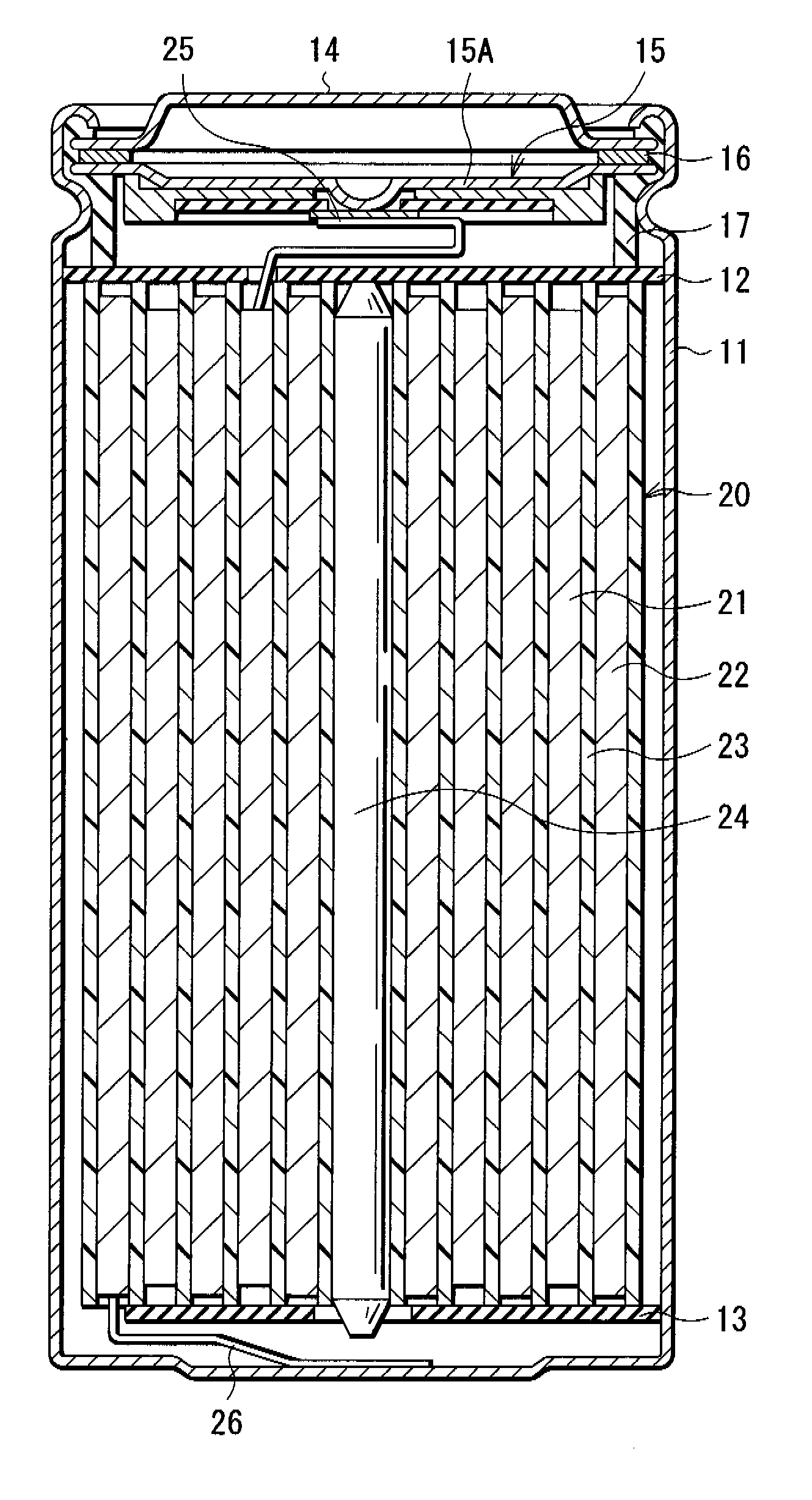
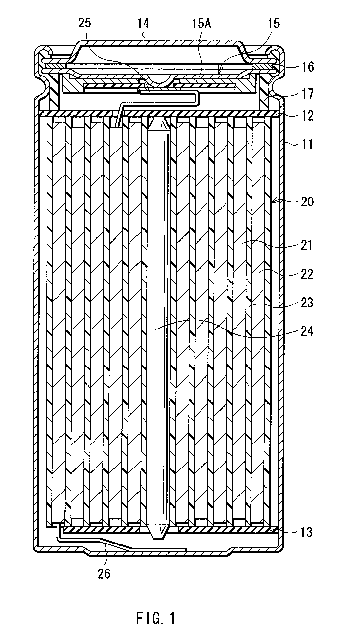
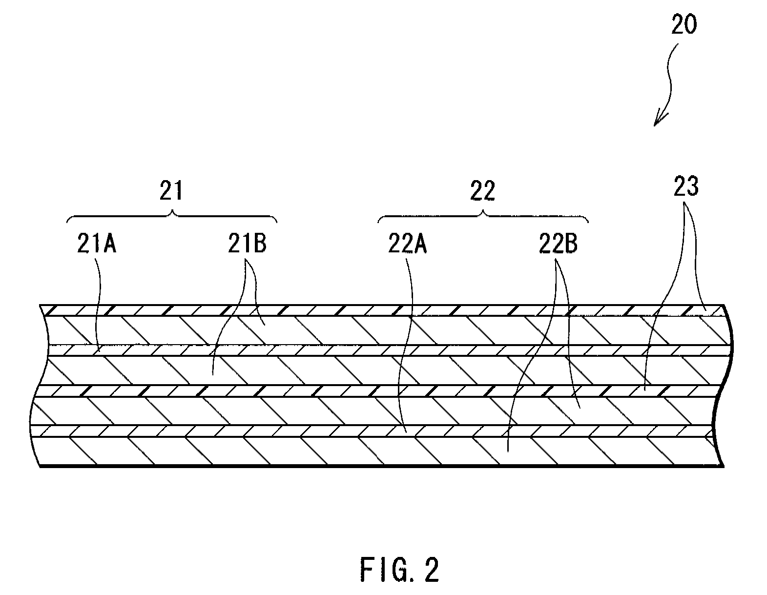
[0071] A secondary battery according to a second embodiment of the invention has the same structure, functions and effects as those in the first embodiment, except that the structures of anodes 22 and 34 are different, so the secondary battery can be manufactured in the same manner. Therefore, in the embodiment, FIGS. 1, 2, 3 and 4 are referred, and like components are denoted by like numerals as of the first embodiment, and will not be further described.

[0072] As in the case of the first embodiment, the anodes 22 and 34 have a structure in which anode active material layers 22B and 34B are disposed on both sides of anode current collectors 22A and 34A, respectively, and each of the anode active material layers 22B and 34B includes an anode material in which an active portion including at least one of silicon and tin as an element and a coating portion of a metal oxide arranged on a part of a surface of the active portion are included, and the ratio of the coating portion to the ac...

examples

[0075] Specific examples of the invention will be described in detail below.


PUM


Abstract

An anode material capable of obtaining a high capacity and superior charge-discharge efficiency, and an anode and a battery using the anode material are provided. An anode includes an anode material including an active portion including at least one of silicon and tin as an element and a coating portion of a metal oxide arranged on a part of a surface of the active portion. The ratio of the coating portion to the active portion is within a range from 0.01 wt % to 10 wt % inclusive. Thereby, a high capacity and superior charge-discharge efficiency can be obtained.

Description

CROSS REFERENCES TO RELATED APPLICATIONS [0001] The present invention contains subject matter related to Japanese Patent Application JP 2005-334162 filed in the Japanese Patent Office on Nov. 18, 2005, the entire contents of which being incorporated herein by reference. BACKGROUND OF THE INVENTION [0002] 1. Field of the Invention [0003] The present invention relates to an anode material including at least one of silicon (Si) and tin (Sn) as an element, and an anode and a battery using the anode material. [0004] 2. Description of the Related Art [0005] In recent years, a large number of portable electronic devices such as camcorders, digital still cameras, cellular phones, personal digital assistants and laptop computers have been emerged, and an attempt to reduce the size and the weight of them has been made. Accordingly, the development of lightweight secondary batteries capable of obtaining a higher energy density has been promoted. Among the batteries, a lithium-ion secondary bat...

Claims


Application Information

Patent Timeline
IPC IPC(8): H01M4/58H01M10/40H01M4/02H01M4/134H01M4/36H01M4/38H01M6/16H01M10/05H01M10/0525H01M10/0566H01M10/0569
CPCH01M4/131H01M4/134H01M4/38H01M4/485H01M10/0569H01M10/0587Y02E60/122H01M4/386H01M4/387Y02E60/10Y02P70/50H01M4/48H01M4/58H01M10/02
Inventor YAMAGUCHI, HIROYUKI
Owner MURATA MFG CO LTD
Learn More