
Aortic lancet

a technology of aortic lancet and aortic valve, which is applied in the field of aortic valve, can solve the problems of lateral nicks protruding from opposite sides of the hole in the vessel wall, affecting the operation of the aortic valve, so as to prevent any accidental cutting

Inactive Publication Date: 2007-05-03
QUEST MEDICAL
View PDF26 Cites 69 Cited by
  • Summary
  • Abstract
  • Description
  • Claims
  • Application Information

AI Technical Summary

Benefits of technology

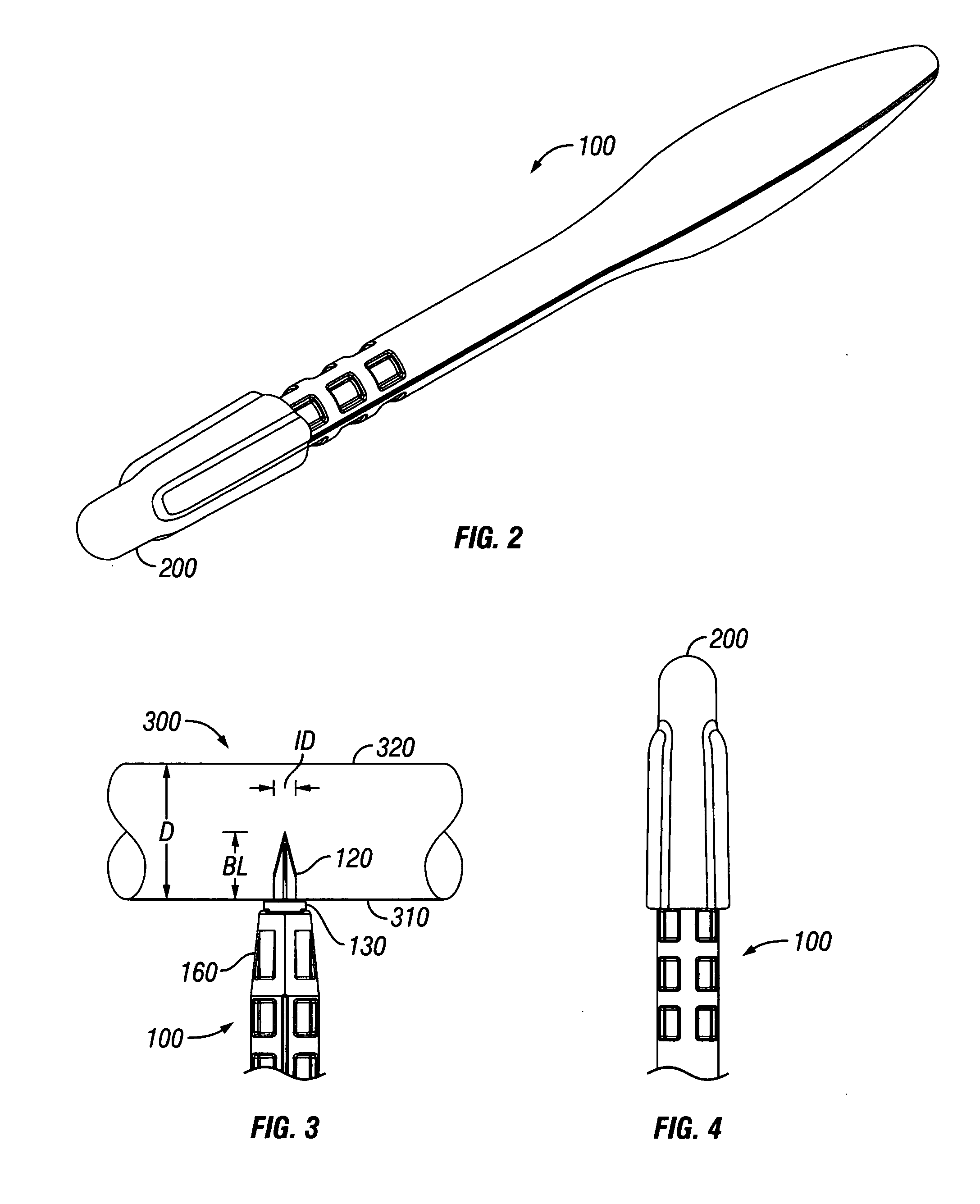
[0008] The present invention relates to an improved system for making a precise incision and circular hole in a vessel wall. In one aspect, the system comprises a lancet having a retractable shield surrounding a blade. The retractable shield helps to prevent any accidental cutting that can occur during surgical conditions. When an incision is made, the shield simultaneously retracts as the blade penetrates the front vessel wall. The blade length is less than the inside diameter of the vessel wall to prevent accidental penetration of the back vessel wall. In one aspect, the system comprises a punch having a tapered cutter with a circumferential edge for receiving an anvil cutting edge. The anvil is placed through the incision in the front vessel wall and actuated to cause a helical shearing force as the anvil cutting edge axially slides past the rotary circumferential cutting edge to produce a clean-cut hole in the vessel wall.

Problems solved by technology

As a result, the connection of the proximal end of the saphenous vein thereto may not be as reliable, and complications during or after surgery may result.
Unfortunately, the diameter of the hole made in the vessel wall is sometimes less than the length of the educated-guess incision made by the scalpel resulting in lateral nicks protruding from opposite sides of the hole in the vessel wall, as illustrated by FIG. 2 of the '022 Patent.
These nicks necessitate special suturing to prevent blood leakage, and add points of weakness at the site of the vessel graft.
However, such an incision necessitates stretching of the tissue for insertion of the aortic punch anvil.
The stretching of the tissue can decrease the patency of the resulting graft or cause aortic dissection wherein the layers of the aortic wall separate from one another.
An additional problem a surgeon faces with making such incision is that the heart, in some procedures, is not arrested and is permitted to beat, which can impart some movement on the vessel that the surgeon is attempting to make an incision.
Such movement can make an accurate incision more difficult.
Further, if a surgeon applies too much pressure and pushes the scalpel or blade too far into the vessel, damage to the opposite or back wall of the vessel can occur.
One problem with prior art punches is that the distal end of the anvil is typically flat, or has a tip with a vertex having a large angle.
As the amount of pressure required increases, the potential for an undesirable fissure or tear in the vessel wall increases as well.
Further, additional pressure can cause undesirable stretching of the tissue remaining after the hole in the vessel has been made.

Method used


Image

  • Aortic lancet
  • Aortic lancet
  • Aortic lancet

Examples


Embodiment Construction

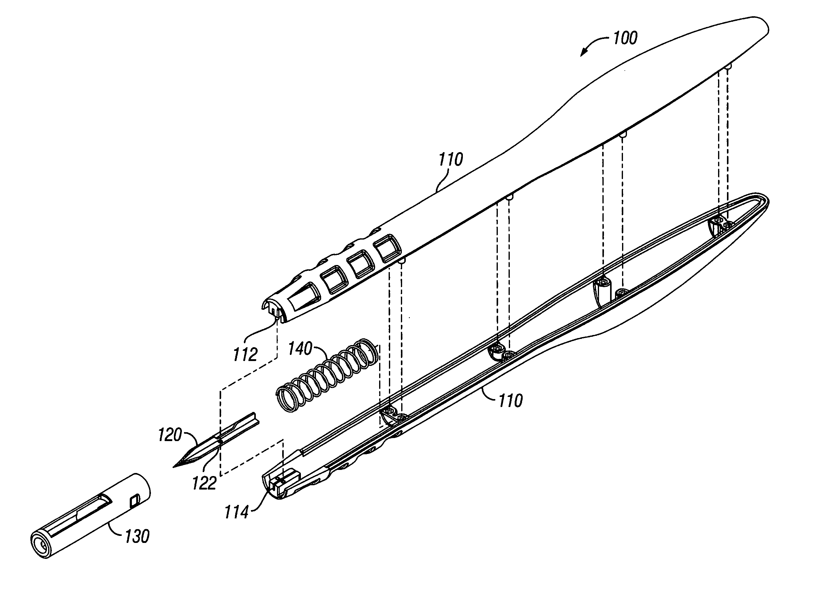
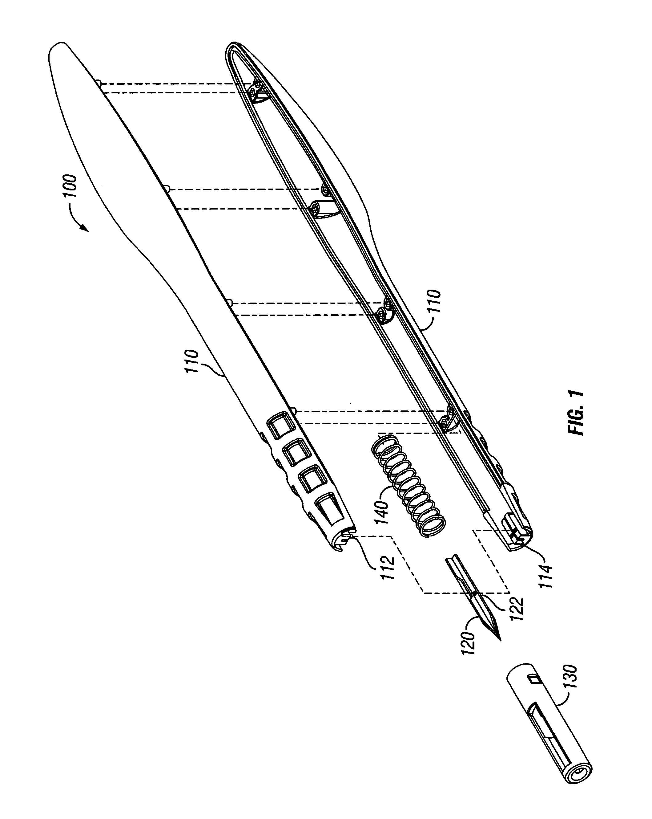
[0017]FIG. 1 is an exploded perspective view of the lancet in accordance with one embodiment of the present invention. The lancet 100 comprises a blade 120 attached to a handle 110. In one embodiment, the handle comprises a first section and a second section that can be removably snap-fit together. In one embodiment, the first section of the handle 110 comprises at least one and preferably two male members 112 disposed through an aperture 122 in the blade 120 and into a female member 114 in the second section to attach the blade 120 to the handle 110. The blade 120 thereby protrudes from the handle 110. A retractable blade shield 130 is slidably attached to the handle 110 and surrounds the blade 120. In one embodiment, the blade shield 130 is clear or transparent so that the blade 120 is visible.

[0018] The blade shield 130 helps to minimize accidental cutting that can occur in surgical conditions. For example, it should be noted that during surgical conditions, slippery fluids such...


PUM


Abstract

A system for making a precise incision and circular hole in a vessel wall, such as the aorta, that eliminates lateral side notches from the aortotomy. In one aspect, the system includes a surgical knife or lancet having a blade surrounded by a retractable shield. In one aspect, the system includes a tissue punch having a rotating circumferential edge for receiving a parabolic-shaped anvil having an anvil cutting edge. The anvil is placed through an incision made by a knife and actuated to produce a hole in the vessel wall.

Description

BACKGROUND OF THE INVENTION [0001] 1. Technical Field [0002] The present invention is directed generally to methods and apparatus for effectuating surgical incisions. More specifically, the present invention is related to methods and apparatus for creating a hole in a vessel wall including an aorta wall. [0003] 2. Description of Related Art [0004] During surgical procedures, such as placement of a ventricular assist device, blood vessel anastomosis, aortotomy, gastrotonomy, enterotomy, or access to other hollow organs and vessels, it is useful to have specialized tools to create a circular opening in the wall of the vessel or organ. Tools have been developed for use in surgery that create such openings. For example, often the goal of heart surgery is to produce a blood flow path around the diseased areas of coronary arteries. A saphenous vein graft can be used by forming an opening in the wall of an ascending aorta, and anastomosing the opening to a proximal end of the saphenous vei...

Claims


Application Information

Patent Timeline
Patent Type & Authority Applications(United States)
IPC IPC(8): A61B17/32
CPCA61B17/0057A61B17/32053A61B2017/1107
Inventor DOLLAR, MICHAEL L.DUBUCLET, VICTOR A. IVERNST, DAVID T.
Owner QUEST MEDICAL
Learn More