
Joining structure between ceramic substrate and power supply connector

Active Publication Date: 2007-05-03
NGK INSULATORS LTD
View PDF4 Cites 5 Cited by
  • Summary
  • Abstract
  • Description
  • Claims
  • Application Information

AI Technical Summary

Benefits of technology

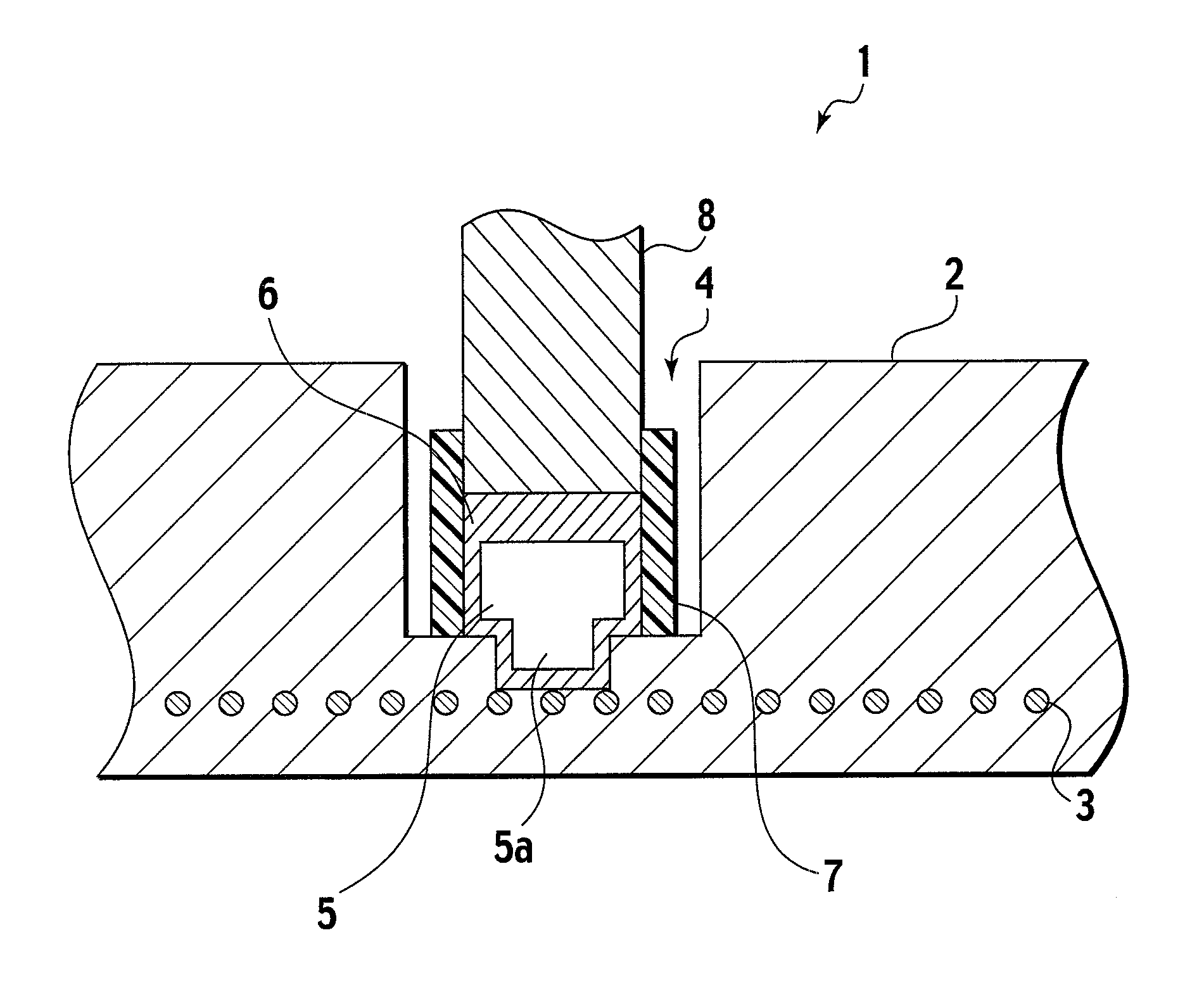
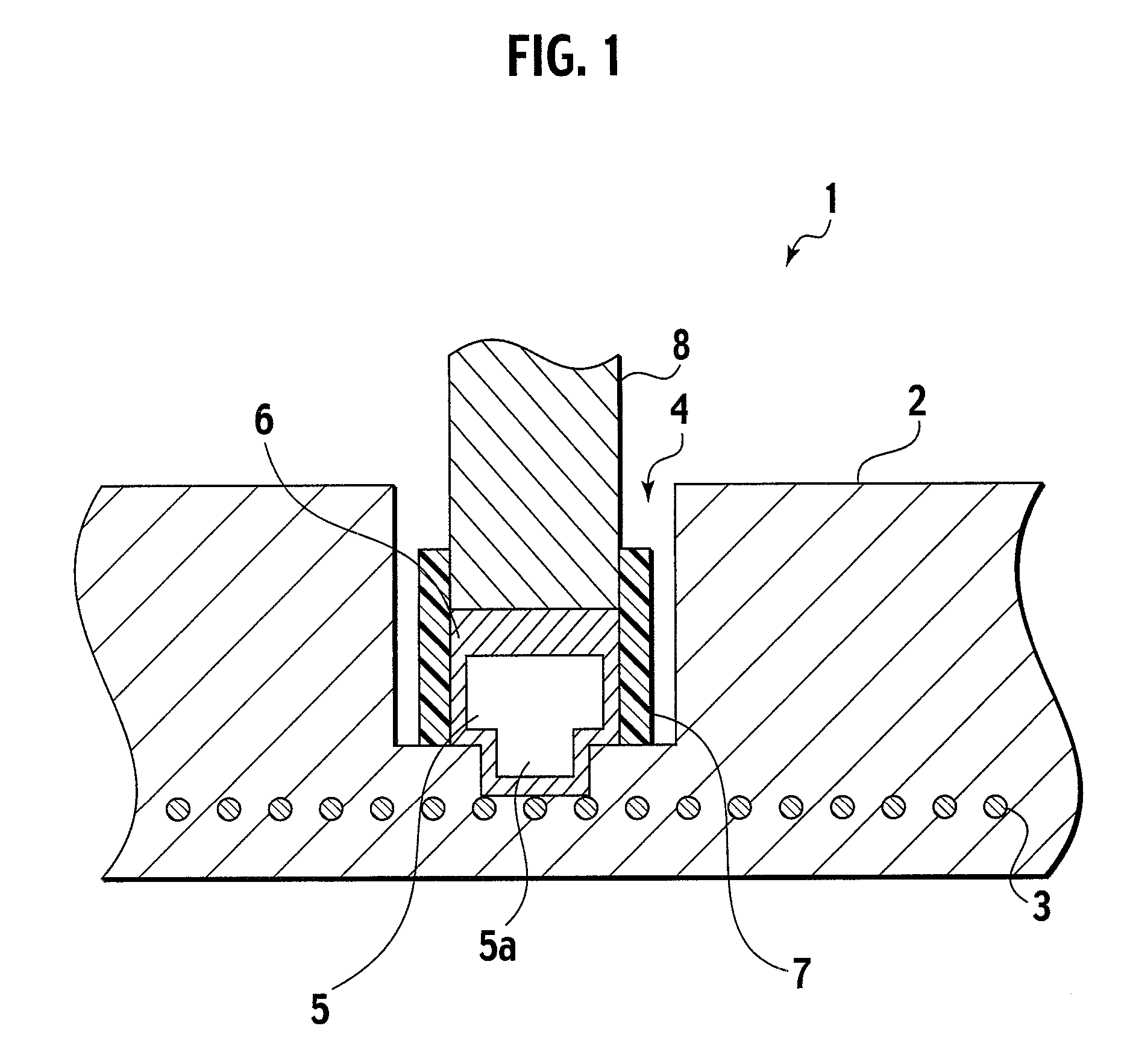
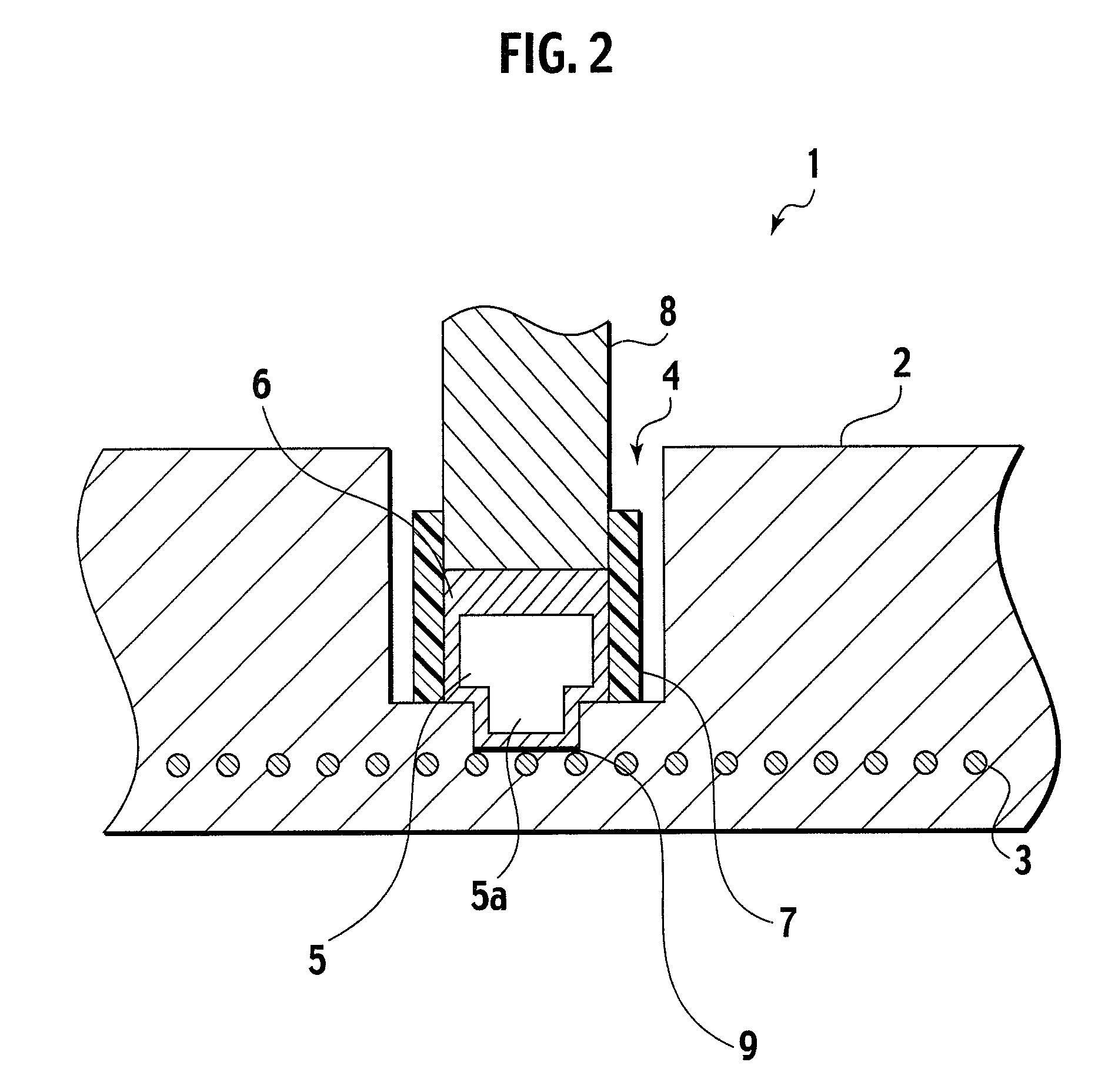
[0004] The device has a structure in which the metal member and the power supply connector are joined to each other in the bottom portion of the opening as described above. Thus, strength of a joining part against bending stress is low, and the power supply connector is likely to be disjoined from the metal member by a bending load from the outside. Moreover, oxygen entering from the opening deteriorates the joining part, particularly, the metal member. Accordingly, life of the joining part (electrically connected) is shortened. Against such a background, there is an urgent market need to provide a joining structure between a metal member and a power supply connector, which can maintain higher joining strength and good electrical connection for a long time.
[0005] The present invention was made in consideration of the foregoing demand. It is an object of the present invention to provide a joining structure between a ceramic substrate and a power supply connector, which can maintain high joining strength and good electrical connection for a long time.

Problems solved by technology

Thus, strength of a joining part against bending stress is low, and the power supply connector is likely to be disjoined from the metal member by a bending load from the outside.
Moreover, oxygen entering from the opening deteriorates the joining part, particularly, the metal member.

Method used


Image

  • Joining structure between ceramic substrate and power supply connector
  • Joining structure between ceramic substrate and power supply connector
  • Joining structure between ceramic substrate and power supply connector

Examples


examples

[0025] Hereinafter, description will be given of some examples of the high-frequency generation electrode device 1 manufactured by use of the manufacturing method described above.

[0026] The FIG. 5 shows results obtained by respectively performing conduction cycle tests on high-frequency generation electrode devices provided with stress relaxation insert members having dimensions of examples 1 to 6, high-frequency generation electrode devices provided with stress relaxation insert members having dimensions of comparative examples 1 to 4, and a conventional high-frequency generation electrode device (without a stress relaxation insert member). Specifically, in the conduction cycle test, a cycle of heating the device from 100 [° C.] to 700 [° C.] at a heating rate of 10 [° C. / min] and, thereafter, cooling the device from 700 [° C.] to 100 [° C.] at an average cooling rate of 7 [° C. / min] in a state where power is being distributed to a RF electrodes is repeated. Note that, in this tes...


PUM


Abstract

A joining structure between a ceramic substrate in which a metal member is buried and a power supply connector which supplies power to the metal member is disclosed. The joining structure includes a counterbore, a stress relaxation insert member, and a brazing member. The counterbore is formed in the ceramic substrate so as to have a large-diameter part and a small-diameter part formed at the bottom center of the large-diameter part. At least a part of the metal member is exposed from the bottom of the small-diameter part. The stress relaxation insert member has a body part and a protrusion and is provided in the counterbore in a state where the body part and the protrusion are fitted into the large-diameter part and the small-diameter part, respectively. The brazing member connects the power supply connector to the stress relaxation insert member, and seals a gap between the counterbore and the stress relaxation insert member.

Description

CROSS REFERENCE TO RELATED APPLICATION [0001] This application is based upon and claims the benefit of priority from a Japanese Patent Application No. TOKUGAN 2005-314603, filed on Oct. 28, 2005; the entire contents of which are incorporated herein by reference. BACKGROUND OF THE INVENTION [0002] The present invention relates to a structure with which to join a ceramic substrate having a metal member buried therein and a power supply connector for supplying power to the metal member (the structure is hereinafter referred to as a “joining structure between the ceramic substrate and the power supply connector.”) [0003] The device has heretofore been put to practical use, which generates high-frequency power and heats a ceramic substrate such as aluminum nitride by electrically connecting a power supply connector to a metal member, such as a metal electrode or a metal resistor, which is buried in the ceramic substrate and thus supplying power to the metal member from the power supply c...

Claims


Application Information

Patent Timeline
IPC IPC(8): H02B1/00
CPCH01L21/6831H01L21/68H02N13/00
Inventor FUJII, TOMOYUKI
Owner NGK INSULATORS LTD
Learn More