Power module fabrication method and structure thereof

a technology of power modules and fabrication methods, applied in the manufacture of printed circuits, printed circuit aspects, basic electric elements, etc., can solve the problems of power module volume reduction, power module shutdown, and inability to efficiently dissipate heat from the housing, so as to improve the heat dissipation efficiency of power modules and simplify the fabrication method. , the effect of saving materials

Active Publication Date: 2007-04-26
DELTA ELECTRONICS INC
View PDF5 Cites 3 Cited by
  • Summary
  • Abstract
  • Description
  • Claims
  • Application Information

AI Technical Summary

Benefits of technology

[0007] An object of the present invention is to provide a fabrication method of a power module and the structure thereof, wherein the heat-conducting plate is inlaid on the housing directly while forming the housing, so as to simplify the fabrication method, secure the heat-conducting plate firmly and raise the heat dissipating efficiency of the power module. Moreover, the pins and the heat-conducting plate are made from the same metal plate for saving material and lowering the fabrication cost.

Problems solved by technology

However, to reduce the volume of the power module is not a simple task if a certain space has to be reserved in the housing or a heat sink is to be attached on the electronic component on the circuit board for dissipating heat.
Moreover, more heat is produced by the high power electronic components in the miniaturized power module, so the heat cannot be dissipated efficiently from the housing and the accumulated heat may cause the shutdown of the electronic equipment.

Method used


Image

  • Power module fabrication method and structure thereof
  • Power module fabrication method and structure thereof
  • Power module fabrication method and structure thereof

Examples


Embodiment Construction

[0027] The present invention will now be described more specifically with reference to the following embodiments. It is to be noted that the following descriptions of preferred embodiments of this invention are presented herein for purpose of illustration and description only; it is not intended to be exhaustive or to be limited to the precise form disclosed.

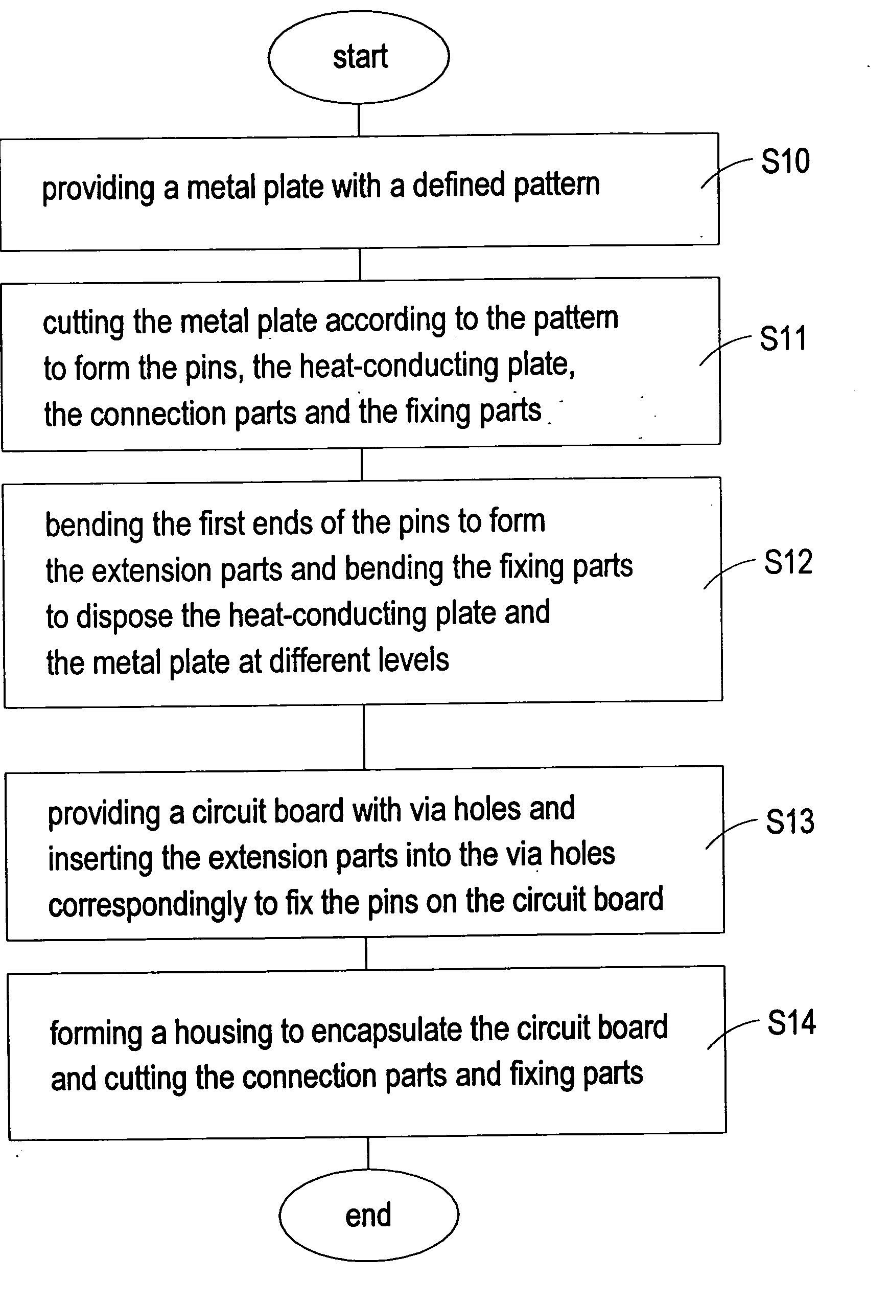
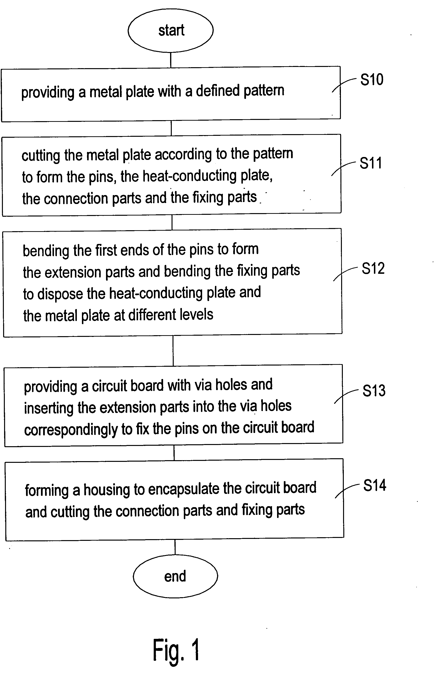
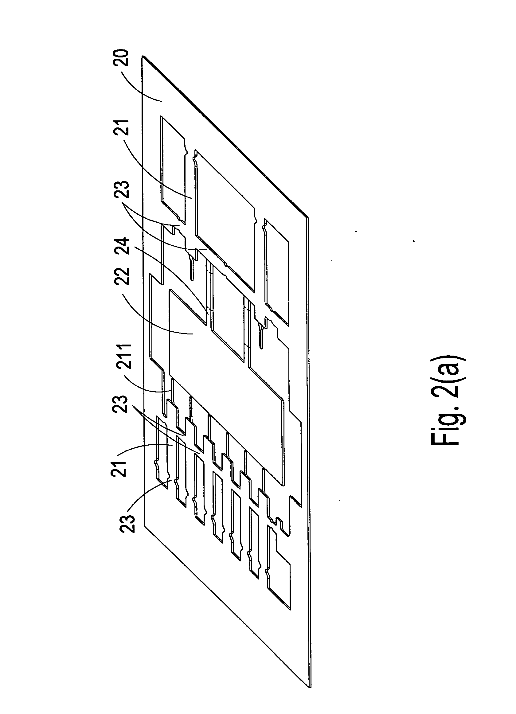
[0028] The power module in the first preferred embodiment of the present invention is a surface mounted device (SMD) power module 2 as shown in FIG. 2(d) by using the fabrication method as shown in FIG. 1 with the metal plate 20 and the circuit board 26 as shown in FIGS. 2(a)-(c).

[0029] Please refer to FIGS. 1 and 2(a)-(c), a metal plate 20 is provided and a pattern is defined on the metal plate 20 (step S10). The metal plate 20 can be any high thermal conductivity material, such as copper, but not limited thereto. Then the metal plate 20 is cut according to the pattern to form a plane structure with a plurality of pins 21, a ...


PUM


Abstract

A power module fabrication method and structure thereof is disclosed. The method includes steps of: providing a metal plate and defining a pattern on the metal plate; cutting the metal plate according to the pattern to form a plurality of pins and the heat-conducting plate, wherein the pin is coupled to each other or to the metal plate via a connection part and the heat-conducting plate is coupled to the connection part via a fixing part; bending a first end of the pin to form an extension part and bending the fixing part to dispose the heat-conducting plate and the metal plate at different levels; providing a circuit board with a plurality of via holes and inserting the extension part into the via hole correspondingly and fixing the pin on the circuit board; forming a housing to encapsulate the circuit board therein, wherein the heat-conducting plate is inlaid on the housing and a second end of the pin is extended out of the housing; and cutting the connection part and the fixing part to separate the pin from each other and from the metal plate and isolate the pin and the heat-conducting plate.

Description

FIELD OF THE INVENTION [0001] The present invention relates to a power module fabrication method and the structure thereof, and more particularly to a fabrication method of a miniaturized power module and the structure thereof. BACKGROUND OF THE INVENTION [0002] Generally speaking, the electronic equipment relies on the power module like adaptor or built-in power for converting the input voltage into the working voltage, therefore the working voltage can drive the electronic equipment. Take the conventional adaptor for example; the structure comprises the upper and lower housings to encapsulate the circuit board therein. The input voltage is converted into the working voltage by the electronic components such as capacitor, resistor, transformer, and diode on the circuit board of the power module for keeping the operation of the electronic equipment. [0003] The voltage converting efficiency of the power module is getting higher with the increasing working efficiency of the electronic...

Claims


Application Information

Patent Timeline
Patent Type & Authority Applications(United States)
IPC IPC(8): H01L23/053
CPCH01L23/49531H01L23/49551H01L23/49568H05K3/0061H05K3/284H05K3/3405H05K2201/1034H05K2201/10924H05K2203/1316H01L2924/0002H01L2924/00
Inventor KUO, CHIN CHIHSIEH, YI HWA
Owner DELTA ELECTRONICS INC
Why Eureka
Try Eureka