
Electronic circuit for ion sensor with body effect reduction

a technology of electronic circuit and ion sensor, which is applied in the direction of instruments, material electrochemical variables, chemical methods analysis, etc., can solve the problems of limiting the precision of measurements carried out by means of isfet, the substrate potential seriously affecting the real characteristics of elements, and the part of the circuit has not yet been applied to the constant voltage and constant current configuration

Active Publication Date: 2007-04-26
CHUNG YUAN CHRISTIAN UNIVERSITY
View PDF3 Cites 12 Cited by
  • Summary
  • Abstract
  • Description
  • Claims
  • Application Information

AI Technical Summary

Benefits of technology

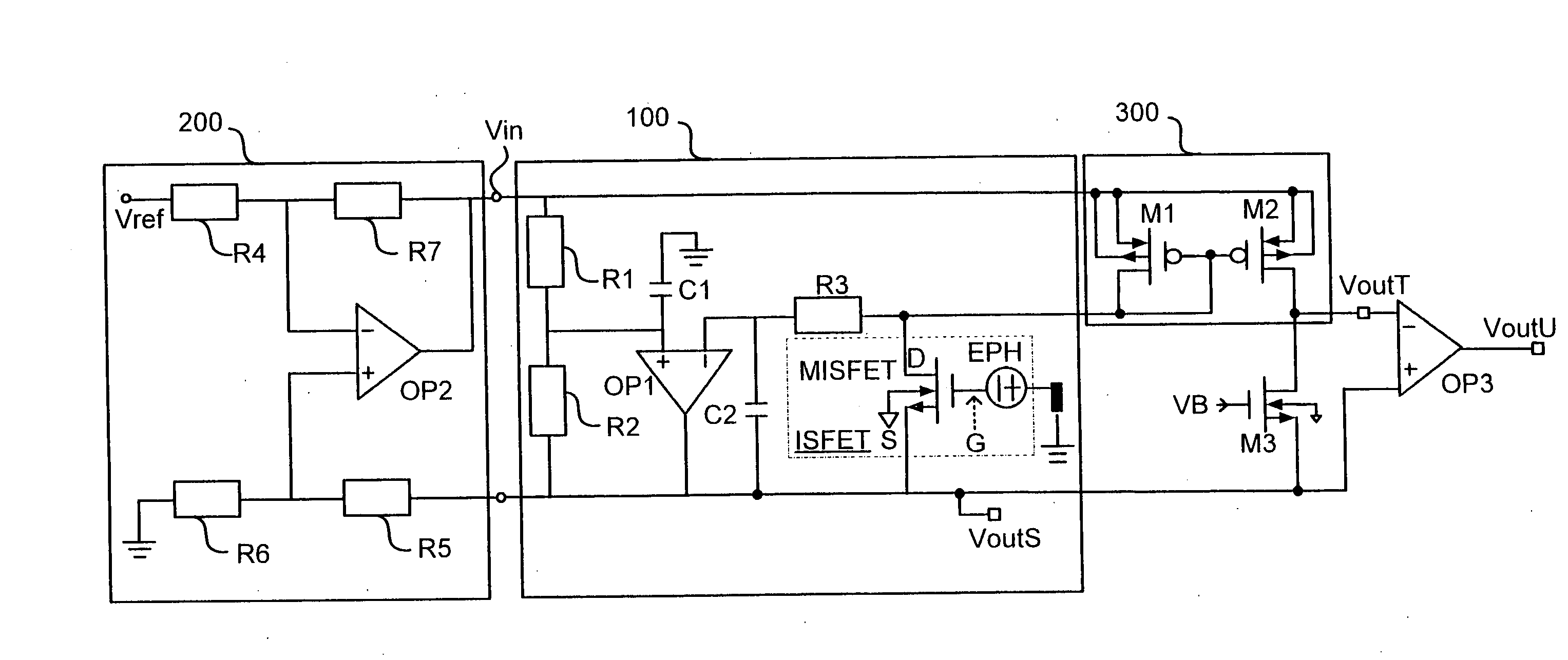
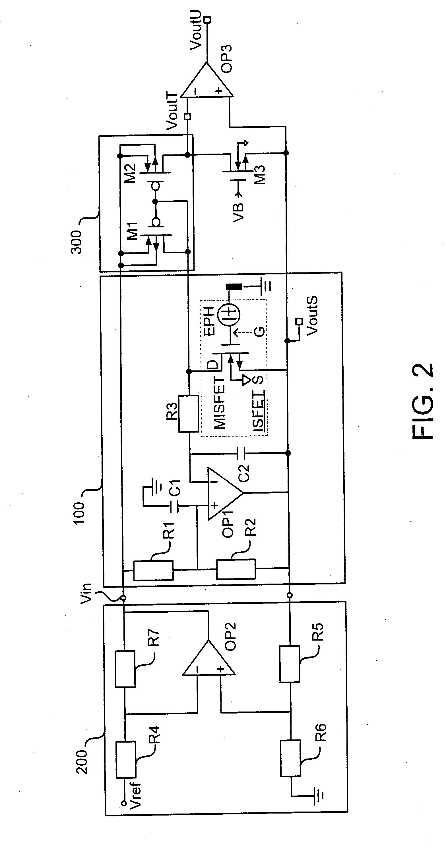
[0014] According to the exemplary embodiments of invention, the bridge-type readout circuit with body effect reduction includes: a bridge-type floating source circuit that is provided with an input and output terminal, and an ISFET having a reference electrode coupled to the ground, wherein one terminal of the ISFET is coupled with the output terminal of the bridge-type circuit; a current mirror is coupled with the bridge-type floating source circuit and consists of a first transistor and a second transistor, for providing a current to the bridge-type circuit; a third transistor connected to the current mirror, for receiving the operating current provided by the current mirror equal to that provided to the ISFET; and a differential amplifying circuit, wherein one input terminal of the amplifying circuit is an input for a reference voltage, and the other input terminal is coupled with the output of the bridge-type circuit, to generate a differential voltage provided to the input of the bridge-type circuit, thereby enabling the ISFET to operate under constant current and constant voltage conditions.
[0018] According to the exemplary embodiments of the invention, an output signal of the bridge-type readout circuit with body effect reduction is constructed to solve the problem of integration of the ISFET and the readout circuit in a standard CMOS technology. Meanwhile, the exemplary embodiments of the invention adopting the differential output configuration can compensate for the undesired effect of the ISFET time and temperature drift at the same time. According to the exemplary embodiments of the invention, it does not require any complicated hardware and the corresponding calculations, and it is suitable for using in all ISFET-type sensors.

Problems solved by technology

The research shows that the ISFET has some undesirable characteristics, including temperature dependence, time drift, and hysteresis, which limit the precision of measurements carried out by means of ISFETs.
Therefore, if the ISFET and the read-out interface are integrated into the same chip, the above-mentioned read-out circuit will face the problem that the substrate potential seriously influences the real characteristics of the elements.
Morgenshtein et al. proposed a new technology in 2004, which eliminates the body effect of ISFET in the read-out circuit of the integrated micro-system; however, some part of the circuit has not yet been applied to the constant voltage and constant current configuration.
However, there was not enough data to prove the compensating effect for this approach.
However, in this case many additional bias voltages must be provided, which increase the complexity of the system.
Some American patents have proposed methods for time and temperature drift compensation, but all those methods required additional circuits and redundant data calculation.
These resulted in large hardware circuits including processors, analog digital converters, digital-analog converters, random access memories, as well as read only memories, and complex calculations to be done on a computer.
Since the Zener diode ZN with floating potentials at both terminals is fabricated in a special technological process, processing of this circuit is not compatible with a standard CMOS technology.

Method used


Image

  • Electronic circuit for ion sensor with body effect reduction
  • Electronic circuit for ion sensor with body effect reduction
  • Electronic circuit for ion sensor with body effect reduction

Examples


Embodiment Construction

[0027] To facilitate further understanding of the object, construction, characteristics and functions of the invention, a detailed description with reference to the embodiments is given in the following.

[0028] Referring to FIG. 2, the electronic circuit for ion sensors with the body effect reduction disclosed in the invention is a kind of readout circuit in a bridge-type configuration. The variation in the threshold voltage VTH can be recorded at the source terminal by using the bridge construction in a part of the bridge-type floating source circuit, grounding the reference electrode Ref, and connecting it to the source floatingly.

[0029] The sensor connected to the bridge-type floating source circuit can be directly exposed to the solution. As long as the species to be measured react with the acceptor on the ion sensing film, a change in the potential is observed at the ion sensing film / electrolyte interface recorded at the output terminal. An ISFET is a kind of ion sensing eleme...


PUM

PropertyMeasurementUnit
temperatureaaaaaaaaaa
time drift coefficientaaaaaaaaaa
temperature coefficientsaaaaaaaaaa

Abstract

An electronic circuit for ion sensor with the body effect reduction includes a bridge-type floating source circuit provided with an input terminal, an output terminal reflecting the change in the potential dependent on ion concentration, and an ion-sensitive field effect transistor (ISFET) wherein one terminal of the ISFET is coupled with the output terminal; a current mirror for providing a current to the bridge-type circuit; a third transistor for receiving the operating current provided by the current mirror, identical to the current provided to the ISFET; a differential amplifying circuit, wherein one input terminal of the amplifying circuit is input with a reference voltage, and the other input terminal is coupled with the output of the bridge-type readout circuit; and a third amplifier to generate a differential output voltage compensated for the body effect, temperature and time drift effects.

Description

CROSS-REFERENCE TO RELATED APPLICATIONS [0001] This Non-provisional application claims priority under 35 U.S.C. § 119(a) on Patent Application No(s). 094136992 filed in Taiwan on Oct. 21, 2005, the entire contents of which are hereby incorporated by reference. BACKGROUND OF THE INVENTION [0002] 1. Field of Invention [0003] The present invention relates to an electronic circuit for an ion sensor, and more particularly to an electronic circuit for hydrogen ion sensitive transistors, configured as a bridge-type floating source with body effect reduction. [0004] 2. Related Art [0005] The development of micro-electronic technology has enabled a very small semiconductor to respond to chemical concentrations. Ion-sensitive field effect transistor (ISFET), a kind of micro-sensing device invented by Bergveld in 1970 and developed quickly thereafter, is a solid state element consisting of a chemical sensing film and a field effect transistor. The ISFET, capable of selective measurements of co...

Claims


Application Information

Patent Timeline
Patent Type & Authority Applications(United States)
IPC IPC(8): G01N27/26
CPCG01N27/4148
Inventor CHUNG, WEN-YAWYANG, CHUNG-HUANGPIJANOWSKA, DOROTA GENOWEFAGRABIEC, PIOTRJAROSZEWICZ, BOHDANTORBICZ, WLADYSLAW
Owner CHUNG YUAN CHRISTIAN UNIVERSITY
Learn More