
Method of manufacturing a fuel cell array and a related array

a fuel cell array and manufacturing method technology, applied in the field of fuel cells, can solve the problems of limited cathodic generation of water, limited overall reaction, and limited use of reformer based systems, and achieve the effect of reducing the need for gaskets and facilitating the molding process

Inactive Publication Date: 2007-04-19
FANNON MEGAN +2
View PDF23 Cites 8 Cited by
  • Summary
  • Abstract
  • Description
  • Claims
  • Application Information

AI Technical Summary

Benefits of technology

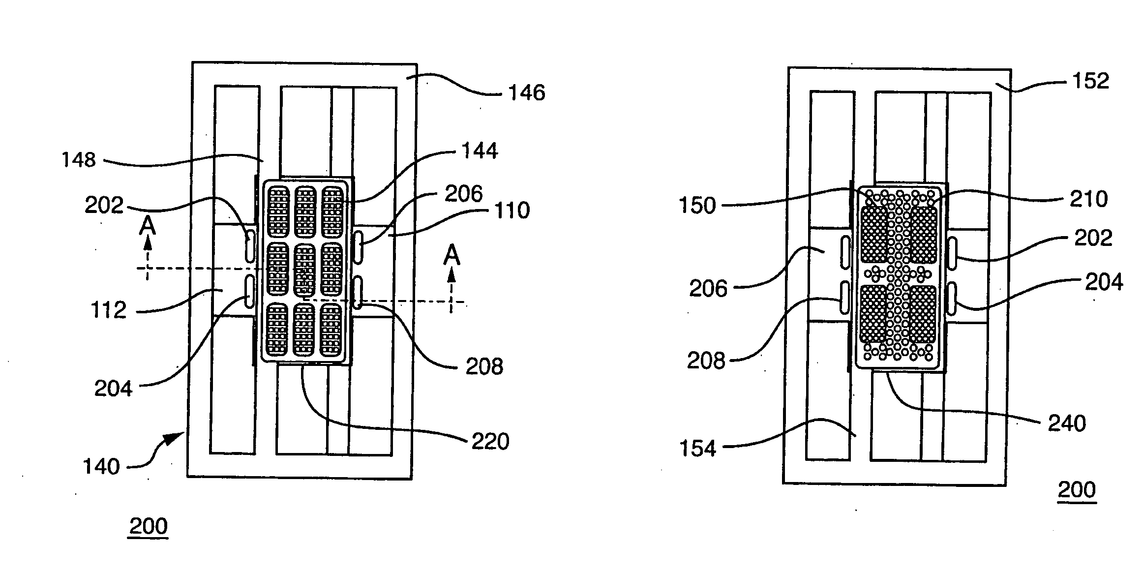
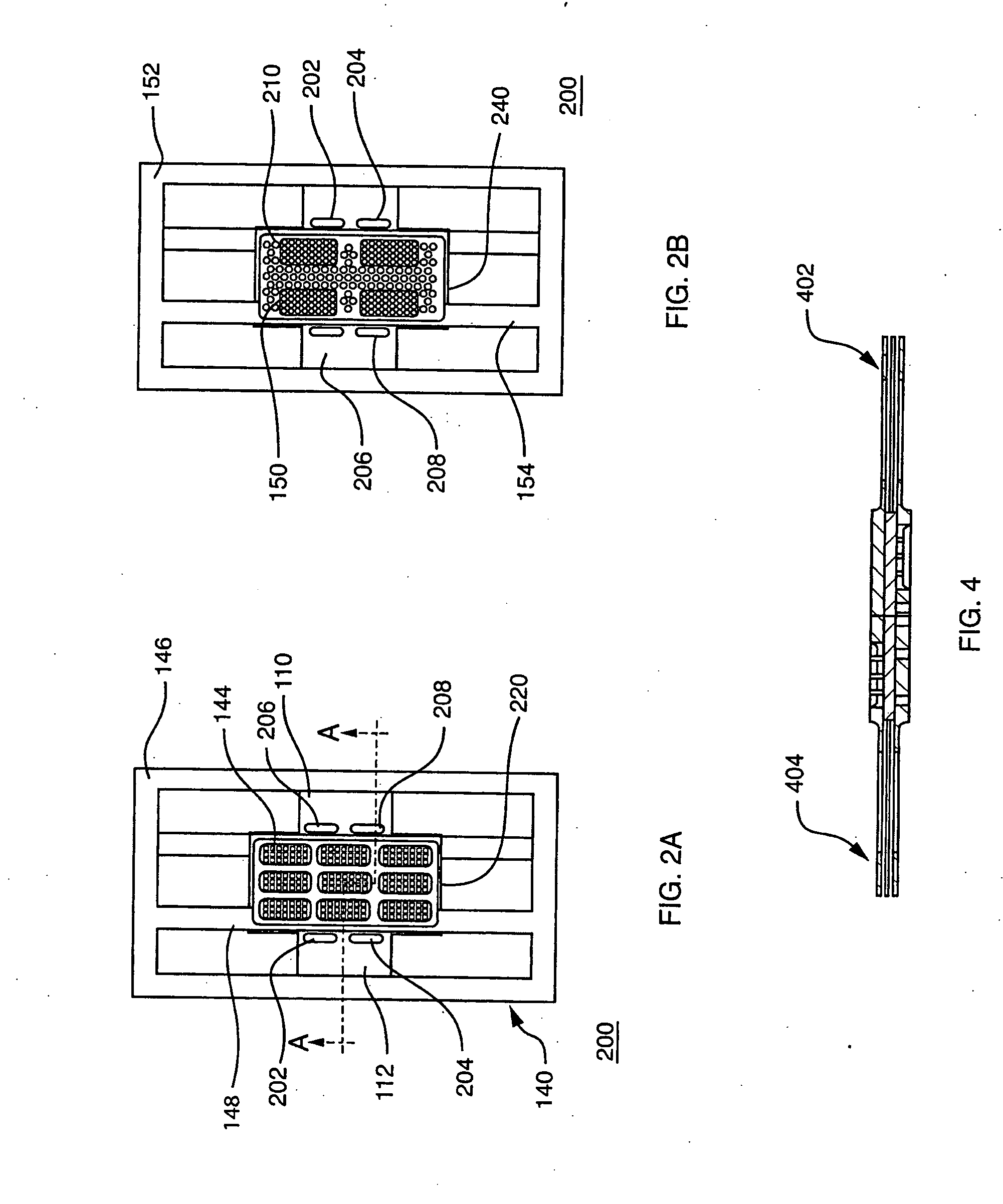
[0016] The deficiencies and disadvantages of prior techniques have been overcome by the solutions provided by the present invention, which is a process for manufacturing a fuel cell and an associated fuel cell array that includes a unique lead frame that integrates current collectors and other components of the fuel cell that are inserted into a mold and thereby sealed. More specifically, the fuel cell components are assembled on a lead frame structure, which is used to facilitate the molding process. The lead frame, containing the previously assembled components of the fuel cell, is inserted into a mold cavity formed by the mold plate and a moldable material, such as plastic, is introduced into the mold cavity to create the frame around the cell. For purposes of this description, the term “mold plate” includes any component that imparts a desired shape or form to the moldable material it receives and which allows the moldable material when solidified, to assume the desired shape as the fuel cell frame. Once the frame is set, the fuel cell frame seals the edges of the fuel cell against leaks. This eliminates the need for gaskets. The frame also holds the components of the cell in compression, without the need for screws and nuts, which are thus completely eliminated.
[0018] In accordance with another aspect of the present invention, current collectors are designed such that they are integrated into the lead frame structural elements in such a manner that the current collectors can act as compression plates within the molded fuel cell. This eliminates the need for separate compression plate components. In accordance with the invention, the mold cavity is designed such that when it closes, the fuel cell is compressed to a predetermined thickness dictated by a desired internal pressure. This allows pressure to be placed evenly across the entire active area of the cell. After the fuel cell is thus constructed and removed from the mold, the now formed plastic frame as well as the structurally enhanced current collectors hold the fuel cell component under a continuous pressure across the surface of the fuel cell. Accordingly, the level of compression obtained by this manufacturing process is both consistent and predictable from cell to cell when compared to the variability in compression observed in cells that are manually assembled.

Problems solved by technology

However, because fuel processing is complex, and requires expensive components, which occupy comparatively significant volume, the use of reformer based systems is presently limited to comparatively large, high power applications.
The overall reaction may be limited by the failure of either of these reactions to proceed at an acceptable rate (more specifically, slow oxidation of the fuel mixture will limit the cathodic generation of water, and vice versa).
Such components themselves can be expensive because they are specially machined.
Furthermore, the assembly of devices that include these fasteners is a time consuming manual process that can also lead to inconsistency in results.
Moreover, the additional parts can add weight, volume and cost to the fuel cell, which if used as a power source for hand-held electronic devices, should be of the smallest form factor possible.
As this is accomplished by hand, this manufacturing technique results in variations in compressions from build to build, in addition to consuming significant assembly time per cell.
In addition to DMFCs, other types of fuel cells, such as hydrogen-gas fueled fuel cells, conventionally require these manufacturing techniques, and have the same disadvantages.
This step, when performed separately, can also be time consuming.

Method used


Image

  • Method of manufacturing a fuel cell array and a related array
  • Method of manufacturing a fuel cell array and a related array
  • Method of manufacturing a fuel cell array and a related array

Examples


Embodiment Construction

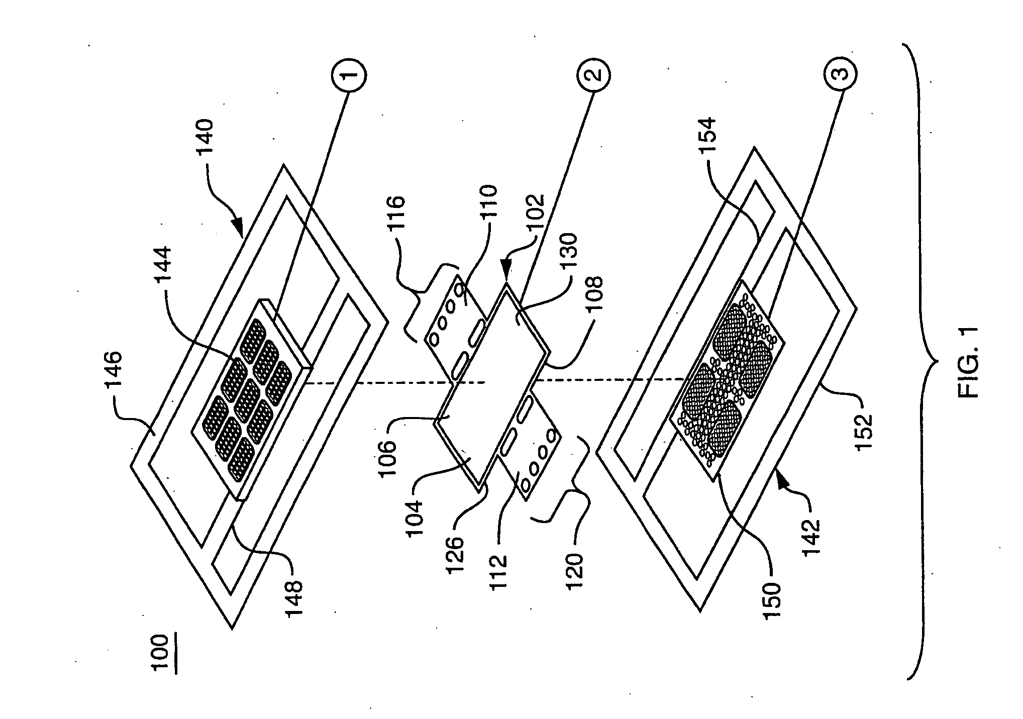
[0034]FIG. 1 is an exploded perspective view of a lead frame assembly and other components of the fuel cell fabricated in accordance with one aspect of the invention. More specifically, the lead frame assembly 100 includes a membrane electrode assembly (MEA) 102. The MEA 102 typically includes a catalyzed membrane electrolyte 104, which may include a protonically conductive, electronically non-conductive membrane. One material that may be used for the catalyzed membrane, which is commercially available is NAFION® a registered trademark of E.I. Dupont de Nemours and Company, a cation exchange membrane based on a polyperflourosulfonic acid in a variety of thicknesses and equivalent weights. The membrane is typically coated on each of its major surfaces with an electrocatalyst such as platinum or a platinum / ruthenium mixture or alloyed particles (not shown). Thus, it is referred to herein as the “catalyzed membrane electrolyte, or the “catalyst coated membrane” (CCM). One face of the c...


PUM

PropertyMeasurementUnit
temperatureaaaaaaaaaa
conductiveaaaaaaaaaa
plastic flowaaaaaaaaaa

Abstract

A sealed fuel cell is provided which has been manufactured with a lead frame assembly encompassing a first and second current collector adapted to serve as lead frame components in an associated mold device. Fuel cell components include a catalyzed protonically conductive, electronically non-conductive membrane that has first and second diffusion layers disposed on opposite sides thereof. The fuel cell components are arranged between the first and second current collectors, and the entire assembly is placed into an insert molding device. A moldable material is introduced into the insert molding device and is allowed to cure in order to seal the edges of the lead frame assembly against leaks to thereby form a sealed fuel cell.

Description

BACKGROUND OF THE INVENTION 1. Field of the Invention [0001] This invention relates generally to fuel cells, and more particularly, to the manufacture of such fuel cells. 2 . Background Information [0002] Fuel cells are devices in which electrochemical reactions are used to generate electricity. A variety of materials may be suited for use as a fuel depending upon nature of the fuel cell. Organic materials, such as methanol or natural gas, are attractive fuel choices due to their high specific energy. [0003] Fuel cell systems may be divided into “reformer-based” systems (i.e., those in which the fuel is processed in some fashion to extract hydrogen from the fuel before it is introduced into the fuel cell) or “direct oxidation” systems in which the fuel is fed directly into the cell without the need for separate internal or external processing. Most currently available fuel cells are reformer-based fuel cell systems. However, because fuel processing is complex, and requires expensive...

Claims


Application Information

Patent Timeline
Patent Type & Authority Applications(United States)
IPC IPC(8): B29C45/14H01M2/08H01M8/10H01M4/94H01M8/02H01M8/24
CPCH01M8/0206H01M8/0247H01M8/0269H01M8/1009H01M8/2455Y02E60/50Y02P70/50H01M8/0273H01M8/242H01M8/2404
Inventor FANNON, MEGANHIRSCH, ROBERTBECERRA, JUAN
Owner FANNON MEGAN
Learn More