
Injection molded parts for vehicles and other devices

a technology for injection molding and parts, applied in the direction of monocoque construction, superstructure subunits, roofs, etc., can solve the problems of increasing the weight of the finished product as well as its manufacturing cost, and the thickness of the body molding is not uniform throughout, so as to improve the overall weight of the body side molding, reduce the cost and manufacturing time, and improve the effect of cooling and cure speed

Inactive Publication Date: 2007-04-19
REHAU INC
View PDF28 Cites 64 Cited by
  • Summary
  • Abstract
  • Description
  • Claims
  • Application Information

AI Technical Summary

Benefits of technology

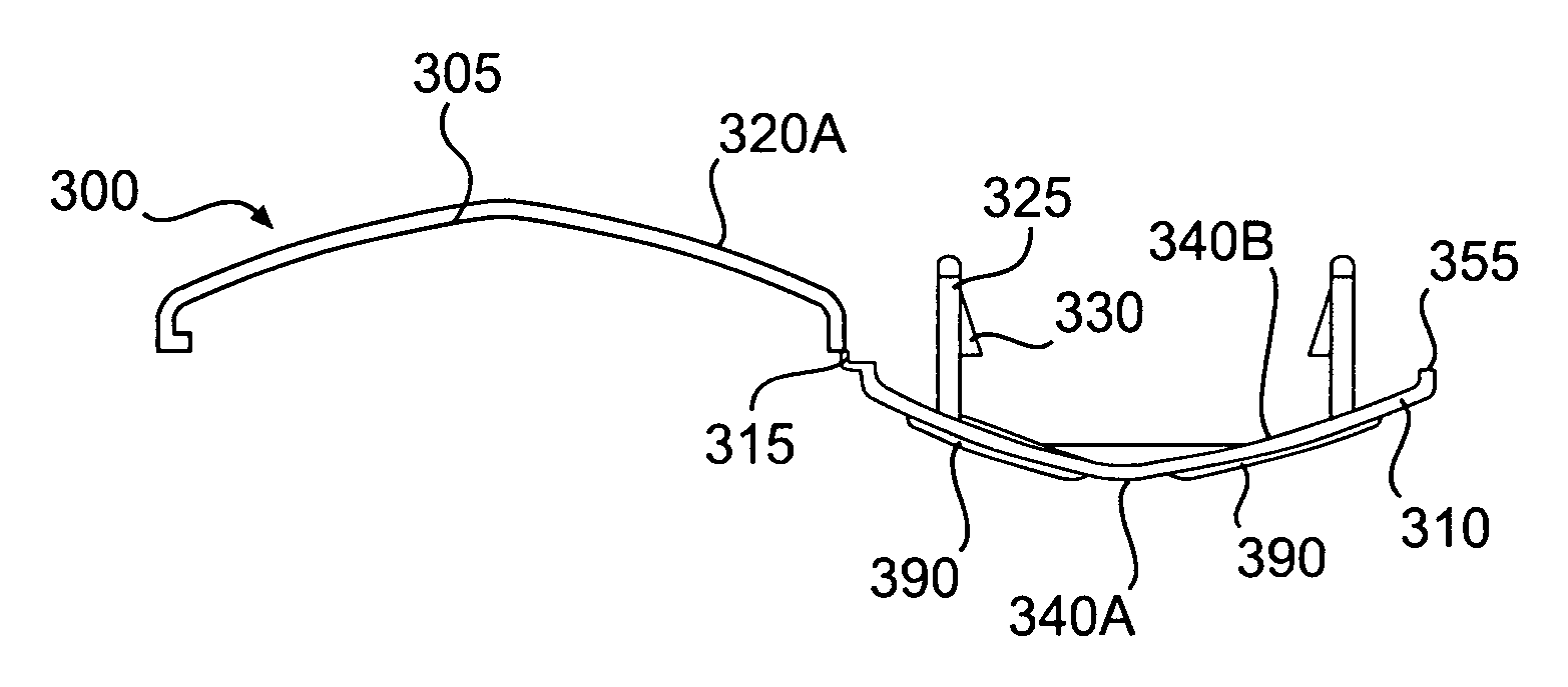
[0018] According to another aspect of the invention, a method of making a vehicle molding having a decorative portion and a support portion connected by a hinge using injection molding includes: providing a single mold to form the decorative portion, the support portion, and the hinge; filling the mold with a moldable material; integrally injection molding the decorative portion, the support portion, and the hinge in the single mold from the moldable material such that the hinge has a thickness less than the thickness of at least one of the decorative and support portions to facilitate pivotal motion of the decorative and support portions and the decorative portion is substantially free of readthrough; curing the moldable material; and removing the molding from the mold. The method may further include the step of integrally forming one or more engagement members on the support portion during the injection molding step. The method may further include the step of integrally forming one or more tension ribs on at least one of the support portion and the decorative portion, such that the tension ribs are disposable between and may contact the support and decorative portions during use. The method may further include the step of forming one or more openings in one of the decorative portion and the support portion and inserting one or more decorative or functional members through the one or more openings. The injection molding step may include forming at least one film gate on at least one of the support portion and the hinge. The injection molding step may include one or more of compression injection molding, gas assist injection molding, water assist injection molding, gas counter-pressure injection molding, and reaction injection molding (RIM). The molding material may include one or more materials including, but not limited to thermoplastic polyolefins, acrylonitrate-butadiene-styrene, polycarbonate, polybutadiene terephthalate, polyethylene terephthalate, nylon, polyvinyl chloride, polystyrene, polypropylene, polyethylene, thermoplastic polyolefin, synthetic rubber, glass, or blends thereof. In this method at least one of the decorative portion and the support portion may have a thickness of between about 1.8 mm to about 2.5 mm. The method may further include one or more finishing steps of washing, drying, and painting at least one of the decorative portion, the support portion, and the hinge.
[0031] As another example, conventional methods form additional features, such as clips, directly onto the trim piece. Such methods, however, are complicated and require many mold actions (actuated movement of lifters within the mold). Moreover, small lifters tend to get hot during use, since they often are too small to place cooling lines in them. If the temperature rises too much, the excess heat can also cause readthroughs and even distortions. In contrast, embodiments of the invention may provide an improved manufacturing process that uses molds shallower than conventional designs, that uses large lifters, which allow water-cooling, and that requires a minimum number of mold actions. For example, the invention may require only about one inch of ejector travel as compared with about six to eight inches of ejector travel for conventional designs. These and other improvements provided by the invention lower cost, reduce complexity, permit creation of a lightweight and shallow mold, improve cycle times, shorten curing / cooling times, and lighten the weight of the finished vehicle molding.

Problems solved by technology

Although use of clips often provides sufficient structural support for the body molding, there are disadvantages to such an attachment.
However, unless relatively thick sidewalls are used, injection molding such parts with thickened tape attachment surfaces provides sink marks that outline the relatively thick solid tape attachment area on the side of the part that is visible when the body side molding is attached to a vehicle body part.
Typically, body moldings are not cast in a uniform thickness throughout to reduce the weight of the finished product as well as its manufacturing cost.
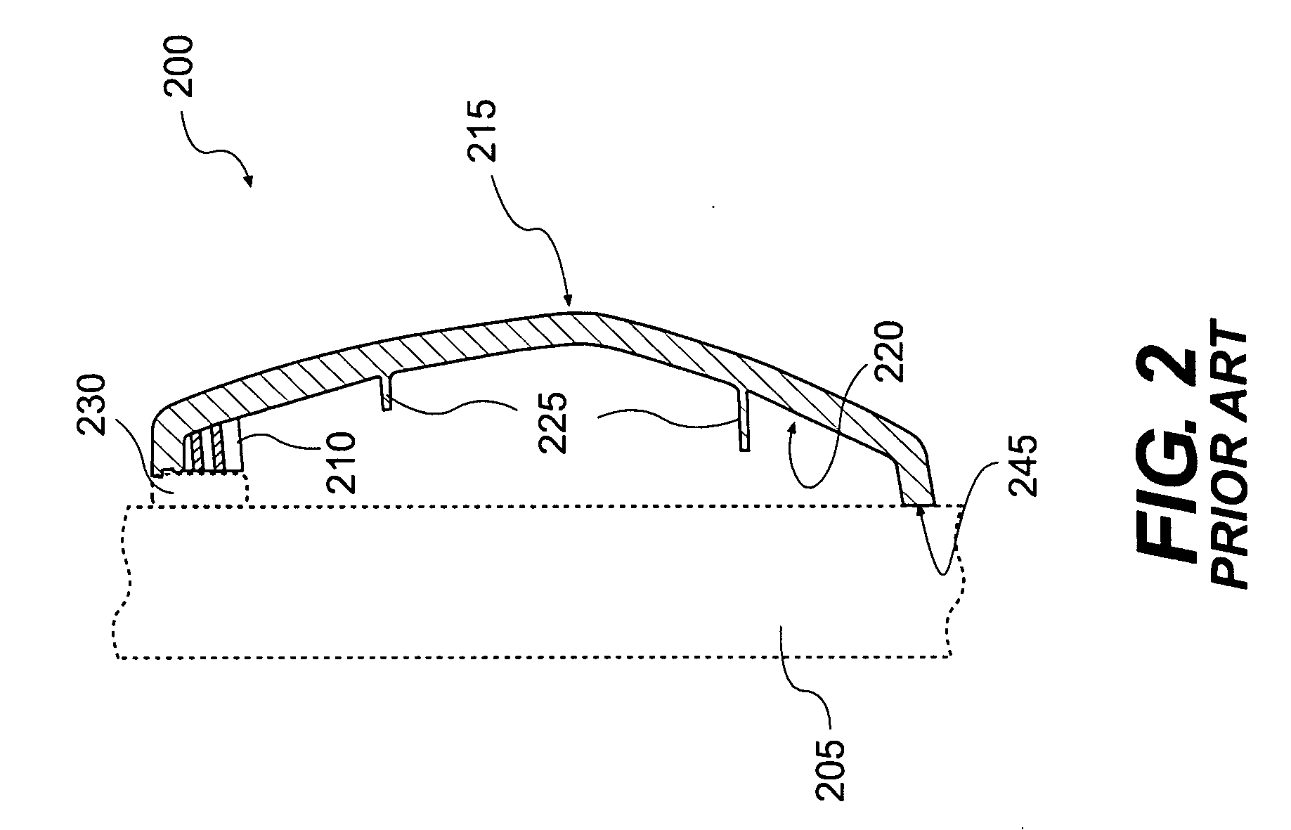
Applicant discovered various problems with conventional two-piece designs.
The thick sidewalls increase the overall weight of the body side molding and lengthen cooling times in an injection molding process.
The increased weight requires extra fasteners and / or adhesive.
Thus, multi-pierce moldings therefore are typically more expensive to make and more labor-intensive to use than single piece moldings.
The drawbacks, however, associated with using extrusion molding are that extrusion molded parts require further processing to obtain clean and ready to use moldings.
For example, other parts such as end caps are often required to obtain smooth edges on extrusion molded parts, thus further complicating the manufacturing process and increasing costs.

Method used


Image

  • Injection molded parts for vehicles and other devices
  • Injection molded parts for vehicles and other devices
  • Injection molded parts for vehicles and other devices

Examples


Embodiment Construction

[0051] The embodiments of the invention and the various features and advantageous details thereof are explained more fully with reference to the non-limiting embodiments and examples that are described and / or illustrated in the accompanying drawings and detailed in the following description. It should be noted that the features illustrated in the drawings are not necessarily drawn to scale, and features of one embodiment may be employed with other embodiments as the skilled artisan would recognize, even if not explicitly stated herein. Descriptions of well-known components and processing techniques may be omitted so as to not unnecessarily obscure the embodiments of the invention. The examples used herein are intended merely to facilitate an understanding of ways in which the invention may be practiced and to further enable those of skill in the art to practice the embodiments of the invention. Accordingly, the examples and embodiments herein should not be construed as limiting the ...


PUM


Abstract

A vehicle part such as a body molding includes a trim piece connected to a bearer piece by a flexible and foldable hinge, which is preferably integrally molded with the trim and bearer pieces in a single injection mold. The trim piece and bearer piece are folded about the molded hinge to rotate towards each other and are snap-fitted together to form an integral body side molding that can be adhesively and / or clippedly affixed to a support surface, such as a vehicle body side panel. Methods for manufacturing and installing such vehicle parts are also disclosed.

Description

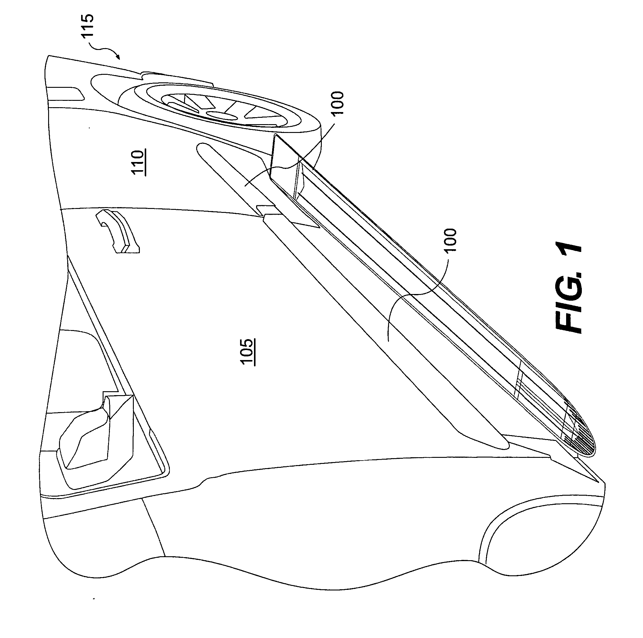
CROSS REFERENCE TO RELATED APPLICATION [0001] This application claims priority under 35 U.S.C. §119(e) to U.S. Provisional Patent Application No. 60 / 727,840, filed on Oct. 19, 2005, the disclosure of which is expressly incorporated by reference herein in its entirety.BACKGROUND OF THE INVENTION [0002] 1. Field of the Invention [0003] The invention relates generally to injection molded parts and, more particularly, to molded parts particularly suited for use as body side moldings for vehicles and other automotive parts. [0004] 2. Background Description [0005] Various types of molded parts are commonly used on cars, trucks and other types of motor sport or recreational vehicles to produce vehicle designs that are visually appealing and / or prevent damage to the vehicle finish, or for other known purposes. In particular, body moldings, claddings, and rocker panels are typically molded plastic parts, usually elongate in shape, that are affixed to the exterior surface of a door, quarter p...

Claims


Application Information

Patent Timeline
Patent Type & Authority Applications(United States)
IPC IPC(8): B60R13/02
CPCB60R13/04
Inventor HAUSER, CHRISTIAN
Owner REHAU INC
Learn More