
Insert moulded surround with integrated lead-out wires

a moulded surround and lead-out wire technology, which is applied in the direction of circuit lead arrangement/relief, earpiece/earphone attachment, intra aural earpiece, etc., can solve the problems of edge support and diaphragm, electrical leads to, for example, electrical coils attached to the piston, and are vulnerabl

Inactive Publication Date: 2007-03-29
SONION HORSENS
View PDF7 Cites 29 Cited by
  • Summary
  • Abstract
  • Description
  • Claims
  • Application Information

AI Technical Summary

Benefits of technology

[0025] It is an advantage of the present invention that electrical signals may be transported across a moulded surround without putting the lead-out wires carrying the signals in danger.
[0026] It is a further advantage of the present invention that the surround material may be chosen independently of the piston material. This advantage provides the flexibility that the surround material may be chosen among soft materials whereas the piston material may be chosen among significantly stiffer materials. As a result, a combined surround and piston may be custom designed to have specific properties such as a diaphragm optimized to have a very low resonance frequency and a flat frequency response. Similarly, a stiffer piston material will cause the diaphragm to have a very large bandwidth.
[0039] By applying the method according to the fifth aspect of the present invention integrated lead-out wires may easily be embedded into a plurality of surrounds by positioning an unbroken lead-out wire across a plurality of injection moulds and injection moulding one or more surrounds by providing an injection mouldable material into the one or more insert moulds. After the injection moulding process the surrounds are separated by cutting the wires which interconnects them.

Problems solved by technology

It is a disadvantage of the edge supports and diaphragms suggested in PCT Publication No.
WO 2005 / 055657 that electrical leads to, for example, electrical coils attached to the piston, are vulnerable due to movements of the diaphragm.

Method used


Image

  • Insert moulded surround with integrated lead-out wires
  • Insert moulded surround with integrated lead-out wires
  • Insert moulded surround with integrated lead-out wires

Examples


Embodiment Construction

[0050] In its most general aspect the present invention relates to a moulded surround with at least one integrated lead-out wire. The lead-out wire is integrated for provided an electrical connection across the moulded surround.

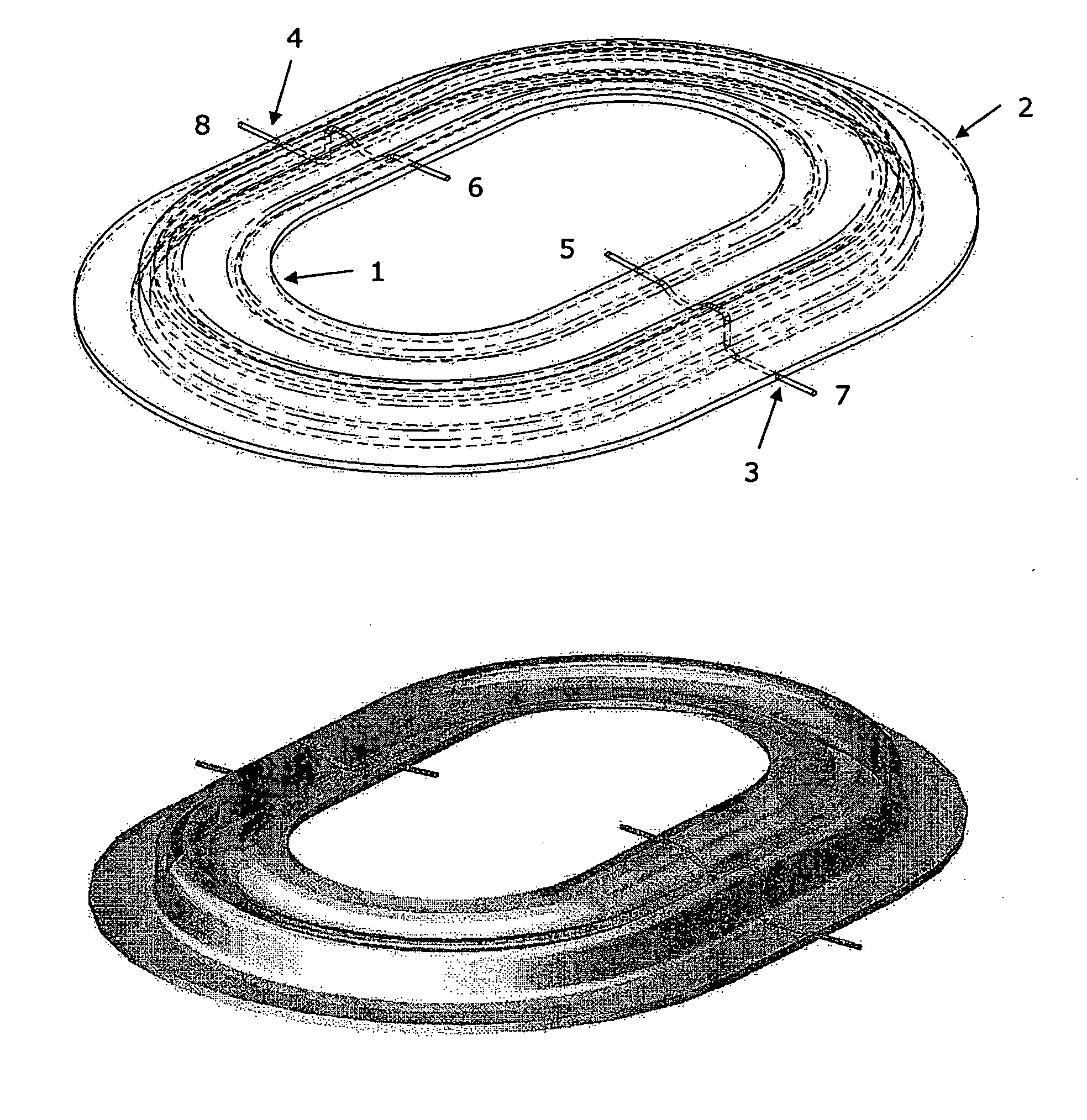
[0051] The moulded surround according to the present invention is depicted in FIG. 1. As seen, the surround has an inner edge 1 and an outer edge 2. The inner edge 1 is adapted for being attached to a piston part (not shown) whereas the outer edge 2 is adapted for being attached to a stiff portion of a magnetic circuit. The piston can be attached to the moulded surround by means such as, for example, gluing, heating or ultrasound-based welding.

[0052] Two integrated lead-out wires 3, 4 are depicted in FIG. 1. Each of these lead-out wires has an inner end 5, 6 and an outer end 7, 8. The inner ends 5, 6 are adapted to be electrically connected to electrical elements / circuits arranged on a piston attached to the inner edge 1. Such electrical elements / circuit ca...


PUM


Abstract

The present invention relates to a suspension member for a diaphragm and to an electro-acoustic transducer applying such suspension member. The suspension member comprises an inner portion being adapted to be attached to a piston, an outer portion being adapted to be coupled to a substantially stationary portion of an associated electro-acoustic transducer, and a flexible member connecting the inner and outer portions. The flexible member comprises at least one electrically conducting element adapted to transport electrical signals across the suspension member.

Description

CROSS REFERENCE TO RELATED APPLICATIONS [0001] This application claims the benefit of priority of U.S. Provisional Patent Application No. 60 / 719,043, filed Sep. 21, 2005, which is hereby incorporated by reference in its entirety.FIELD OF THE INVENTION [0002] The present invention relates to a moulded surround with integrated lead-out wires. In particular, the present invention relates to moulded surround of silicone, rubber, or any other soft material. In addition, the present invention relates to a custom designed diaphragm being constituted by a soft surround and a significantly stiffer piston of, for example, a polyimide, aluminium, nylon, or flex print. BACKGROUND OF THE INVENTION [0003] PCT Publication No. WO 2005 / 055657 relates, in general, to methods for manufacturing vibrators for electro-acoustic transducers and, more particularly, to a method of manufacturing a vibrator for an electro-acoustic transducer, such as a miniature loudspeaker to be used in mobile communication t...

Claims


Application Information

Patent Timeline
Patent Type & Authority Applications(United States)
IPC IPC(8): H04R9/06
CPCH04R1/06H04R1/1016H04R7/20H04R25/00H04R2499/11H04R2231/003H04R2307/204H04R2307/207H04R31/00H04R7/02H04R9/02H04R7/18
Inventor ANDERSENJOHANNSEN, LEIF
Owner SONION HORSENS
Learn More