
Image forming method and image forming apparatus

a technology of image forming and forming method, which is applied in the direction of electrographic process apparatus, instruments, developers, etc., can solve the problems of insufficient charge density of toner, slow charge rise, and occurrence of such defects as toner splashing or background smear of images, and achieve excellent offset resistance, excellent low temperature fixing property, and excellent cleaning

Active Publication Date: 2007-03-15
RICOH KK
View PDF15 Cites 33 Cited by
  • Summary
  • Abstract
  • Description
  • Claims
  • Application Information

AI Technical Summary

Benefits of technology

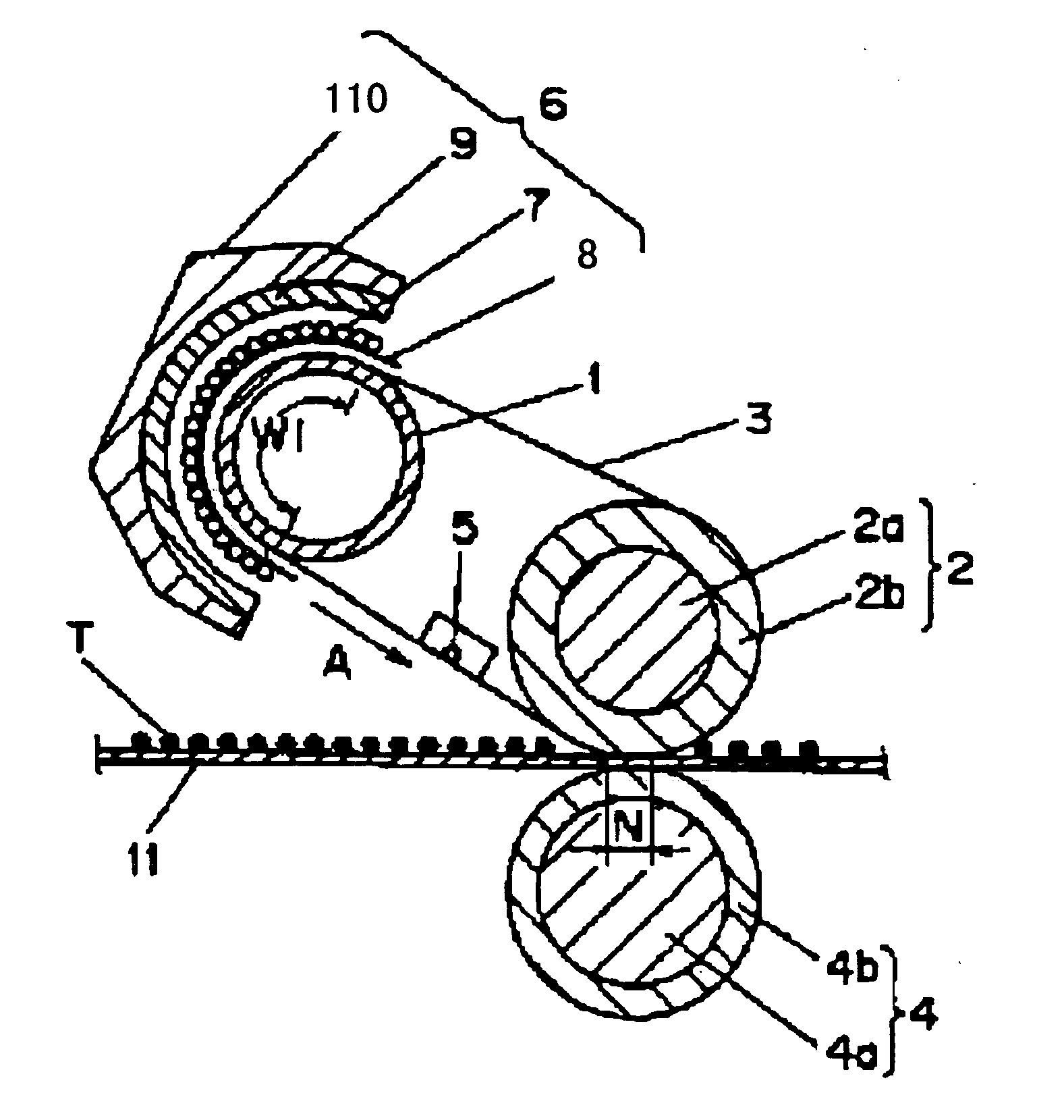
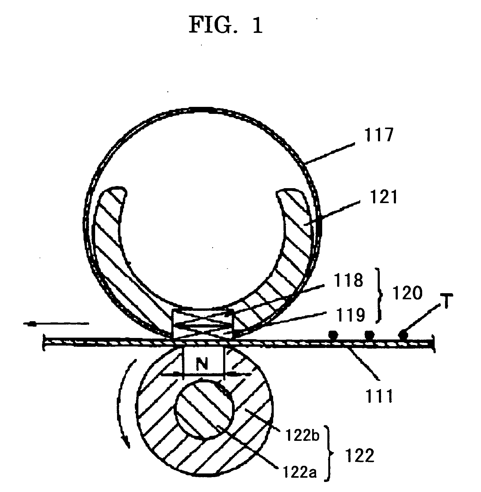
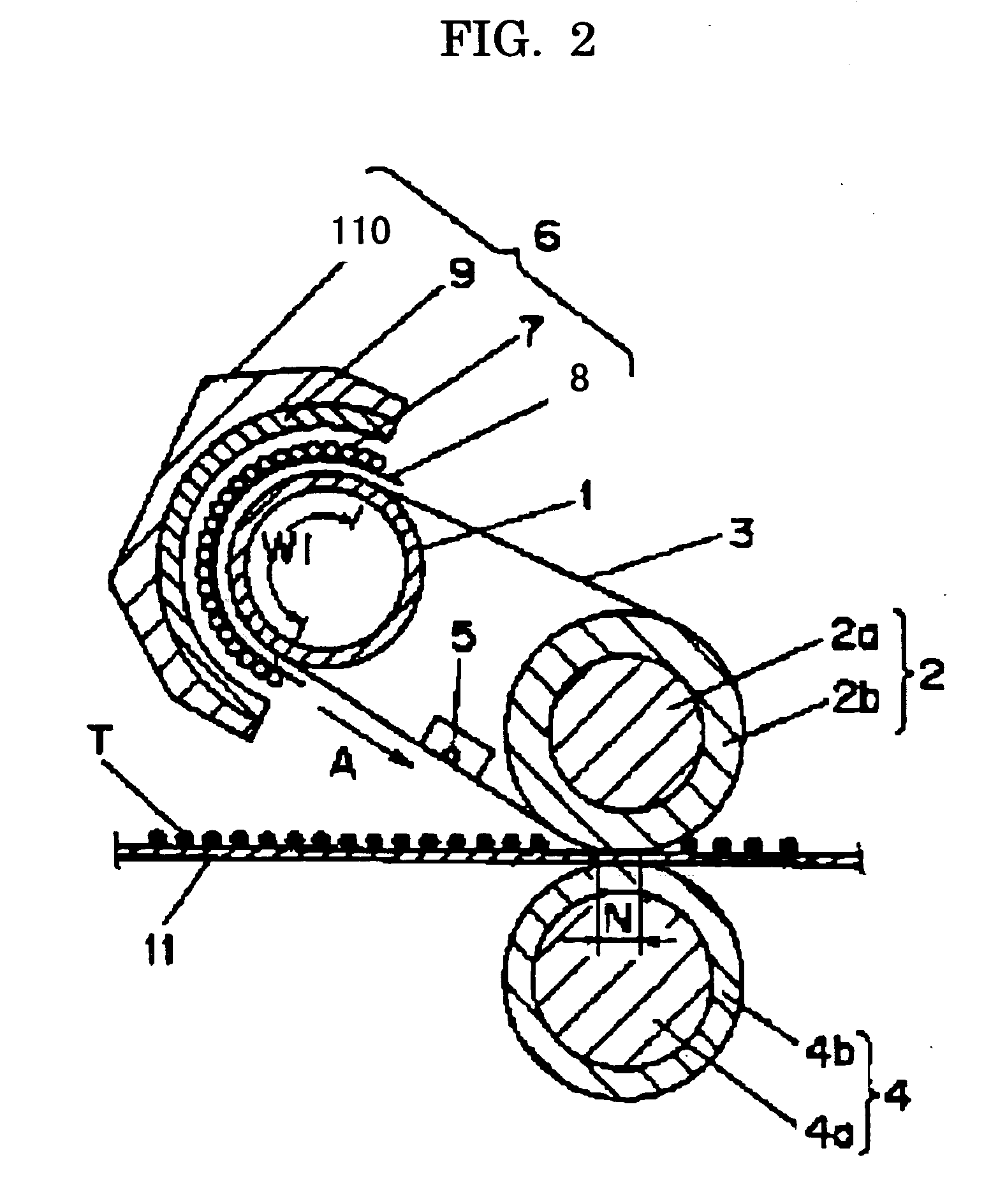
The present invention provides an image forming method and apparatus using a toner with excellent cleaning properties, chargeability, and low-temperature fixing property. The toner has inorganic fine particles dispersed in a near-surface region of the toner base particle, which helps to improve its cleaning performance. However, the use of a deformation treatment process to achieve good cleaning properties may result in a decrease in the contact frequency of concavities on the toner surface with a carrier, leading to slow charge rise and potential defects in image quality. To address this issue, a charge control agent is added to the toner to interact with the inorganic fine particles and make up for the lack of sufficient charge density. The resulting toner has excellent offset resistance and low-temperature fixing properties, and can be fixed using an electromagnetic induction heating system. The image forming apparatus includes a latent electrostatic image bearing member, developing unit, transfer unit, and fixing unit, which work together to produce high-quality images with no background smear.

Problems solved by technology

However, in toner subjected to such deformation treatment, since the contact frequency of concavities on the surface with a carrier comes to be decreased, toner comes to obtain no sufficient charge density, and there will be slow charge rise in the beginning, or less density.
Thus, there may be the occurrence of such defects as toner splash or background smear of images.

Method used


Image

  • Image forming method and image forming apparatus
  • Image forming method and image forming apparatus
  • Image forming method and image forming apparatus

Examples


manufacturing example 1

-Synthesis of Organic Fine Particle Emulsion-

[0379] Into a reaction vessel equipped with a stirrer and a thermometer, 683 parts of water, 11 parts of a sodium salt of a sulfate ester of methacrylic acid ethylene oxide adduct (Eleminol RS-30, manufactured by Sanyo Chemical Industries Ltd.), 80 parts of styrene, 83 parts of methacrylic acid, 110 parts of butyl acrylate, 12 parts of butyl thioglycolate, and 1 part of ammonium persulfate were fed, and stirred at 400 revolutions per minute for 15 minutes to obtain a white emulsion. This emulsion was warmed to a system temperature of 75° C. and then reacted for 5 hours. Further, 30 parts of a 1% aqueous ammonium persulfate solution was admixed thereto, and the resulting mixture was matured at 75° C. for 5 hours to synthesize an aqueous dispersion of a vinyl resin (a copolymer of styrene-methacrylic acid-butyl acrylate-a sodium salt of a sulfate ester of methacrylic acid ethylene oxide adduct). This product was to be Fine Particle Dispers...

manufacturing example 2

[0405] Except that preparation of an oil phase of Manufacturing Example 1 is changed as follows, Toner (2) and Developer (2) were prepared as in Manufacturing Example 1.

-Preparation of Oil Phase-

[0406] Into a reaction vessel equipped with a stirring rod and a thermometer, 500 parts of Low Molecular Polyester 1 (manufactured by Sanyo Chemical Industries, Ltd., RS801)), 30 parts of carnauba wax, and 850 parts of ethyl acetate were fed, warmed to 80° C. under stirring, held for 5 hours as it is at 80° C. , and thereafter cooled to 30° C. over 1 hour. Then, using a beads mill (Ultra-viscomill (manufactured by Imex Corp.), wax is dispersed on the conditions of solution feed velocity: 1 kg / hr, disk circumferential speed: 6 m / sec, 0.5 mm zirconia beads loading: 80% by volume, and pass number: 3 times. Subsequently, in the vessel, 110 parts of Bk Master Batch 1, 620 parts of inorganic fine particles (organo silica sol MEK-ST-UP(solid content concentration (ER)=20%), average primary partic...

manufacturing example 3

[0410] Except that preparation of an oil phase of manufacturing example 1 is changed as follows, Toner (3) and Developer (3) were prepared as in Manufacturing Example 1.

-Preparation of Oil Phase-

[0411] Into a reaction vessel equipped with a stirring rod and a thermometer, 500 parts of Low Molecular Polyester 1 (polyester resin (manufactured by Sanyo Chemical Industries, Ltd., RS801)), 30 parts of carnauba wax, and 850 parts of ethyl acetate were fed, warmed to 80° C. under stirring, held for 5 hours as it is at 80° C. , and thereafter cooled to 30° C. over 1 hour. Then, using a beads mill (Ultra-viscomill (manufactured by Imex Corp.), wax is dispersed on the conditions of solution feed velocity: 1 kg / hr, disk circumferential speed: 6 m / sec, 0.5 mm zirconia beads loading: 80% by volume, and pass number: 3 times. Subsequently, in the vessel, 110 parts of Bk Master Batch 1, and 500 parts of ethyl acetate were put, and mixed for 1 hour, to obtain a dissolved product. This product was ...


PUM


Abstract

To provide an image forming method including forming a latent electrostatic image on a latent electrostatic image bearing member, developing the latent electrostatic image using a toner to form a visible image, transferring the visible image to a recording medium, and fixing a transfer image transferred on the recording medium, wherein the toner includes a toner base particle containing at least a binder resin, a colorant and an inorganic fine particle, and a charge control agent; and wherein the condition Xsurf>Xtotal is satisfied (where Xsurf is an average proportion of the inorganic fine particles in a near-surface region of the toner base particle, Xtotal is an average proportion of inorganic fine particles in the whole toner base particle.

Description

BACKGROUND OF THE INVENTION [0001] 1. Field of the Invention [0002] The present invention relates to an image forming method and an electrophotographic image forming apparatus such as printers, reproduction devices, and facsimiles. [0003] 2. Description of the Related Art [0004] Recently, with respect to image forming apparatuses such as printers, copiers, and facsimiles, the market demand of energy saving and speeding up is growing stronger. To obtain these performances, it is important to achieve improvement in heat efficiency of a fixing unit for use in an image forming apparatus. [0005] In an image forming apparatus, by image forming processes such as electrophotographic recording, electrostatic recording, or magnetic recording, a toner image not having been fixed is formed on a recording medium such as recording sheets, printing papers, photosensitive papers, electrostatic recording papers by an image transfer method or a direct method. In fixing units for fixing such a toner i...

Claims


Application Information

Patent Timeline
Patent Type & Authority Applications(United States)
IPC IPC(8): G03G15/20
CPCG03G9/0827G03G9/09708G03G9/09716G03G9/09725G03G2215/2035G03G15/2064G03G2215/0602G03G2215/2016G03G2215/2032G03G15/2007G03G15/20
Inventor NAKAYAMA, SHINYANAKAJIMA, HISASHISUGIURA, HIDEKISASAKI, FUMIHIROKOTSUGAI, AKIHIROMOCHIZUKI, SATOSHI
Owner RICOH KK
Learn More